My h bridge requires 5v 1 amp. I have a 5v 500mA and another 5v 850mA power supply lying around. Can I join the +ve of both and send that signal to the h brdige so that it can have enough current of 1 A ?
Asked
Active
Viewed 3.2k times
3 Answers
5
Possibly. Possibly not. It depends on whether your power supplies have linear or foldback current limit.
The problem is that the power supplies don't have exactly the same output voltage. The power supply with the highest output voltage will provide all the current that the circuit is requiring until it reaches it's current limit.
What happens then depends on the current limit circuit inside the power supply. If it has linear current limit, its' voltage collapses down to the point where the other power supply begins to supply current.
All is good.
However, if that first power supply has foldback current limit, it will effectively drop out of circuit and the other power supply will attempt to supply all of the current. It, too, will go into current limit. And the output voltage will fall.
You have to test your particular power supplies and see how they behave while in current limit.
Dwayne Reid
- 23,390
- 2
- 35
- 67
1
Looking at this from a mathematical standpoint we can explore this concept by looking at the equivalent circuit, specifically the Thevenin equivalent to start.
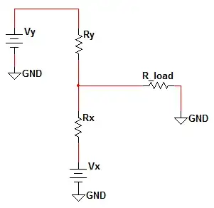
Below is the circuit you are suggesting to build (including the output impedance of each source):
Rearranging things a bit you will agree that the following the same circuit:
We we have is a simple potential divider between Vy and Vx. The process of finding the Thevenin equivalent is simple. First, find the open-circuit voltage and then the short-circuit current. The former can be found by disconnecting the load and calculating the voltage. Since we know this is a potential divider circuit we have:
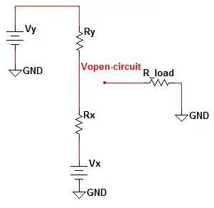
$$V_{open-circuit} = V_x + (V_y - V_x)\frac{R_x}{R_x + R_y}$$
Then we find the short-circuit current. To do this, simply short the output node to ground and determine the drawn current. In this case, the current is simply that which is drawn from each source independently.
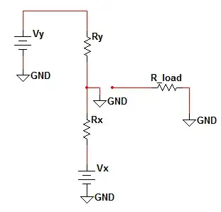
$$I_{short-circuit} = I_{V_y} + I_{V_x} = \frac{V_y}{R_y} + \frac{V_x}{R_x}$$
And then, by the Thevenin Theorem, the equivalent circuit has voltage source with magnitude equivalent to the open-circuit voltage and an output impedance equal to the open-circuit voltage over the short-circuit current.
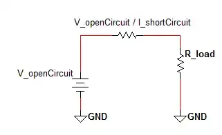
$$V_{open-circuit} = V_{TH} = V_x + (V_y - V_x)\frac{R_x}{R_x + R_y}$$ $$R_{TH} = \frac{V_{open-circuit}}{I_{short-circuit}} = \frac{V_x + (V_y - V_x)\frac{R_x}{R_x + R_y}}{\frac{V_y}{R_y} + \frac{V_x}{R_x}}$$
Therefore, mathematically this is acceptable, but will it yield the results you intend for this combination to provide? It depends on the power supplies being connected.
sherrellbc
- 3,431
- 6
- 35
- 62
-
1Explanations of downvotes is always helpful. – sherrellbc Feb 14 '15 at 15:33
-
1Voted you back up to 0, but my guess is the down vote was because you provided a theoretical answer when the questioner was clearly looking for something more practical. – virtualxtc Aug 27 '18 at 21:30
0
Generally speaking this won't work, unless the power supplies are specifically designed for such operation. Some bench or stackable system power supplies have a tracking/cascading mode for this purpose (Share a single regulation loop).
a) If the power supplies are able to sink current, the following scenario may occur:
The internal voltage regulator always has a certain regulating margin/accuracy. Imagine for a moment that this is +/- 0.2%. For a 5V (4.99 to 5.01V) supply this would mean a potential voltage difference of 0.02V over a very low wiring resistance. At for example 0.001Ω wire resistance this would result in a 'circular' current of 20A!!!! between both units.
b) If the power supplies don't sink current the excessive "circular' current flow won't occur, however mutual influencing of internal voltage regulation loops may still result in unexpected behaviour.
Work arounds:
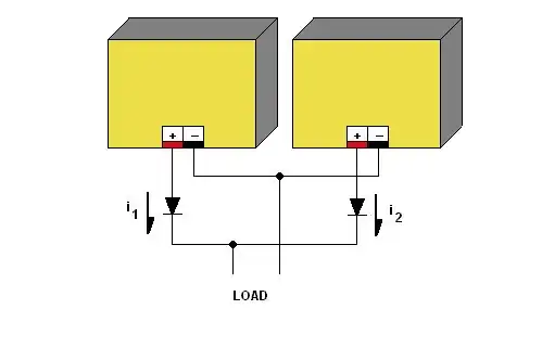
1) You could tie both output together via conventional diodes which solves the problem. However this solution has disadvantages:
- A voltage drop (typ. 0,7- 1V)
- Output is actually no longer regulated since the voltage drop varies with the drawn current.
- The biggest problem however is that due to differences in the dynamic resistance of the PS and wiring and diode resistance the current distribution between both can vary widely (Not 50/50 as one may expect).
2) You could make use of what is called ideal diodes, which are basically MOSFETs with the accompanying circuitry. These components exist in a variety of current ratings have a very low voltage drop and therefore perform much better with respect to the above. Google "Ideal diode". You may want to read this.
3) Best solution is generally a single PS or PS with parallel tracking mode.
-
Most power supplies can only source current, not sink it. You do *not* get circulating currents as you described above. With batteries: Yes. You get circulating current as the battery with the higher voltage attempts to charge the battery with the lower voltage. But not most power supplies. – Dwayne Reid Feb 14 '15 at 17:04
-
Using diodes to isolate the power supplies from each other won't help in this situation. And ideal diodes either require external power *or* the MOSFET acts like a piece of wire once it is turned ON. – Dwayne Reid Feb 14 '15 at 17:06
-
@ Dwayne: I don't see why that would be a problem. So-called ideal diodes are specifically made to "or" power sources and can even be used as a rectifier. You are right to say that many PS won't sink current, however the TS can't know this unless he or she tries. If it can sink current the PS probably won't survive the test, if it can't there's still a high chance the feedback loops go "haywire". There's also no guarantee that currents are distributed equally. Diodes solve at least part of this problem. Like I pointed out using diodes is a 'work around' not a 'preferred solution'. – Ambiorix Feb 14 '15 at 23:40
-