PWM is the way to modulate the output, but something else is needed too since you want the current to be precise. Set it up so that when the microcontroller pin is high, you get the maximum current with good precision, then go down from there using PWM.
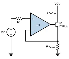
At 300mA you want to keep the LED current off the nicely regulated supply. Whatever you have driving the regulated supply is probably a little higher voltage and not so well regulated. A nice trick is to drive the LED from a NPN in controlled current sink mode. This means drive the base directly from the microcontroller output pin, the emitter goes to ground via a resistor, and the LED is connected between a positive supply and the collector. If the microcontroller power supply is well regulated, then the voltage accross the resistor will be reasonably fixed and sets the current the transistor will draw when on.
For example, if the micro is running from a nice 3.3V supply, then the emitter voltage will be about 2.6V. 2.6V / 300mA = 8.7 Ohms. You will have to experiment a little to get the exact current you want since the exact B-E drop is hard to guess, but this will be a good starting point. Actually I'd pick the nearest standard resistor size down, like 8.2 Ohms, then calibrate the rest in the micro. You should get a little more than 300mA with 8.2 Ohms, but whatever you do get should be pretty repeatable. It will also be quite independent of the unregulated voltage the LED is connected to, as long as it's enough to run the LED. Let's say you measure 320mA when the micro output pin is high. You then run the PWM from 0 to 94.8% to get your 0-300mA full scale.
For most purposes, figuring out this scale factor once in the lab and hard coding it will be good enough.