2

I was wondering what would be the voltage of the node which is connected to 1K and 4K resistors? sometimes I think I need to add up the two voltage sources( 13-2=11V) but I wonder maybe it is just 13V . can you give me some insights please? I am really carious to know when can we add up and when we cannot? what if the polarity of 2V source was the other way around? ( I think then that would 13+2=15V).

The main goal is to find V0 here is what I have tried so far. I would appreciate your comments on that.

enter image description here

enter image description here

Scott Seidman
  • 29,274
  • 4
  • 44
  • 109
user65652
  • 356
  • 7
  • 21
  • It's 11V. You reference it to ground, and from ground you have +13 and -2V so +11V total. The 13V is a power source, not a node measurement; you can't just ignore the 2V source. – I. Wolfe Feb 03 '15 at 22:45
  • then what would be V0( negative polarity) ? zero because it is connected to the ground? – user65652 Feb 03 '15 at 22:47
  • I am lot here, so the ground is 2 V ? – user65652 Feb 03 '15 at 22:48
  • Vo is the voltage from the + to the minus. So it is the voltage of the + side in reference to ground. – I. Wolfe Feb 03 '15 at 22:49
  • Ground is just a reference point, it is the point we take as being 0V. The 2V source is a negative source in reference to ground. So it outputs -2V into the circuit. Just think of ground this way: How do you know 2V is 2V? You know because it is 2V higher than ground. – I. Wolfe Feb 03 '15 at 22:52
  • can I assume that positive polarity of the Op Amp is zero since it is connected to the ground ? – user65652 Feb 03 '15 at 22:58
  • Please label the nodes of your circuit so you can say "node A" instead of "the node which is connected to 1K and 4K resistors". – The Photon Feb 03 '15 at 23:03
  • And yes, things that are connected by ideal wires are at the same potential, and the potential of the ground node is, by definition, 0 V. – The Photon Feb 03 '15 at 23:04
  • I did my analysis and I came up with V0=0V, is that correct? – user65652 Feb 03 '15 at 23:06
  • I rolled back your edit. Much better to leave your line of reasoning in, show you've put some thought into the question, and let people clear you up where you don't have it right. If you want to then go after Vout, do some work again, modify your question to show it, and we'll help you where you're missing. We're not in the biz of handing out homework answers – Scott Seidman Feb 03 '15 at 23:14
  • You might want to read [this](http://electronics.stackexchange.com/questions/33145/op-amp-analysis-when-are-the-negative-feedback-rules-applicable) to get a better handle on analyzing op-amp circuits. – The Photon Feb 03 '15 at 23:20
  • I modified the question, please have a look at it and let me know, thanks – user65652 Feb 03 '15 at 23:25
  • 1
    Think about where the current through the 6k resistor goes. Apply KCL to node C – Scott Seidman Feb 03 '15 at 23:42
  • one the one hand, we know that current going through the op amp is zero, also the input of op ampt is zero which makes Node zero to be 0 zero, but still current going through to the output of op amp through 12 ohm resistor, it is so weird, why is that ? – user65652 Feb 03 '15 at 23:45
  • Again, FORMALLY apply KCL to node C -- work through the equation you get, and tell us the current going through the 12K resistor. – Scott Seidman Feb 04 '15 at 00:02
  • I found V0=-12 V – user65652 Feb 04 '15 at 00:07
  • Now you're talking! If point B is really 6 volts, which I didn't check, then Vout would be -12 volts, as the output stage is an inverting amp with a gain of -2. – Scott Seidman Feb 04 '15 at 01:52
  • @user65652 Same comment for OP as for the answerer - this would be a much better question if you had just the electrical part as an image, and that big block of text beneath the circuit as actual text. Words on pictures aren't easily searchable. – Adam Lawrence Feb 06 '15 at 21:30

3 Answers3

3

I am really carious to know when can we add up and when we cannot?

When two two-terminal elements are in series, the voltage across the combination is equal to the sum of the voltages of the branches.

When two two-terminal elements are in parallel, the total current through the combination is equal to the sum of the currents of the two branches.

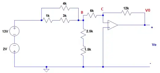
But the problem is C=0 since the input of the op-amp is zero volts on both sides, ... does that mean V0 is zero volts also?

We say that negative feedback drives node C to zero, but what we really mean is just that it drives it really close to zero. Since C is close to zero but not exactly zero, and the gain of the op-amp is really large (like 100,000 or 1,000,000) then V0 isn't exactly zero.

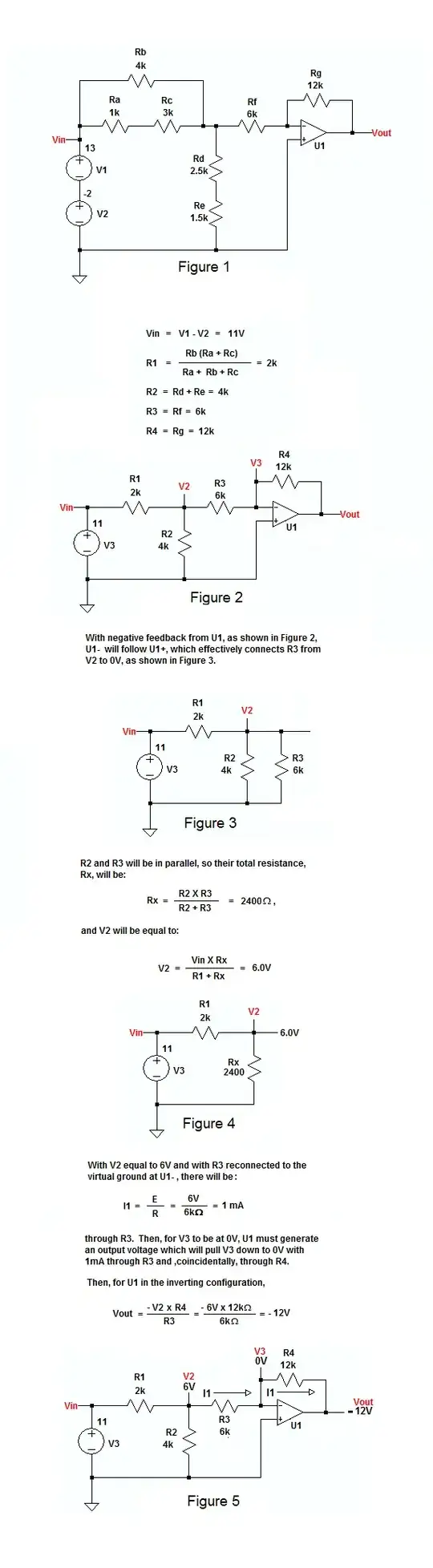
Having calculated the output voltage as -12 V, and assuming the gain is 100,000 (just a typical number, check the datasheet of your op-amp for an appropriate value for your device), you can see that node C is really at about 0.12 mV. You can see that this value doesn't appreciably change the analysis of the input circuit (and in fact this value could be totally inaccurate due to other op-amp non-idealities like input offset voltage).

If you really want to know how big this effect is, the easiest way is to simulate your circuit with a non-ideal op-amp model in a SPICE-like simulator.

The Photon
  • 126,425
  • 3
  • 159
  • 304
  • Thanks for that. I did my analysis and I came up with V0=0V, is that correct? – user65652 Feb 03 '15 at 23:04
  • I haven't solved the whole circuit, but I don't think that's the correct solution. If you simplify the resistor combinations and name your nodes, it would be easier to explain why. – The Photon Feb 03 '15 at 23:07
  • well I did that. but the thing is the input of the Op amp is 0V, does not that mean that V0=0V too? the node that is connect is to 6k and 12k is 0V also – user65652 Feb 03 '15 at 23:09
  • 1
    Well, since node A is at 11 V, then node B must be somewhere between 0 and 11 V. Then the current through R5 must be positive. And that means, for negative feedback to work, current through R6 must be positive. And that means Vo < 0. (You see how much easier this would be if you labeled your nodes and components? Then I would have used your names instead of just making some up and you'd know what I'm talking about) – The Photon Feb 03 '15 at 23:10
  • Ok, I try to label the nodes and edit the question in a bit. thanks – user65652 Feb 03 '15 at 23:12
  • I modified the question, please have a look at it and let me know, thanks – user65652 Feb 03 '15 at 23:24
3

The output calculates to -12V. Thevinize the - input which is at 0 volts, assuming the Av of the opamp is large. That turns the junction point "B" into 6V as "C" is almost 0.00V.

Wow! Cut and paste doesn't work here. No MathCAD for you!

6K*4K/(6K+4K)=2.4K resistance to ground at "B"

Thevinizing: 2.4K*11V/(2K+2.4K)= 6V with 6K series resistance (Point "B" to - in)

(12K/6K*)-1 = -12V . Guess you could use Norton, or worse Thevinin (N+1) but why?

wa9vez
  • 59
  • 2
  • Posting answers to HW questions like this isn't as good as guI ding the user to the solution – Scott Seidman Feb 04 '15 at 01:56
  • Instructions explicitly say to answer question. Question was "how many" not "how do I". Engineer vs "educator" issue. Apprentices need to sort out how to set up and solve the problem for themselves. IMHO, that means showing them intermediate signposts, leaving an accurate breadcrumb trail so they can work the problem and own the solution. Plagiarizing another's solution is no net gain. I must also comment I appreciate the artistry of the graphical explanation. Most excellent! – wa9vez Feb 05 '15 at 15:53
1

One picture is worth a thousand words:

enter image description here

EM Fields
  • 17,377
  • 2
  • 19
  • 23
  • Just a small correction: In Fig. 5 we have R2=4k (instead of 2k); nice calculation. – LvW Feb 04 '15 at 09:50
  • thanks a lot, even though I finished it myself, but it is good to see someone else's solutions. – user65652 Feb 04 '15 at 13:36
  • I think this would be a much better answer with the schematic figures as separate images, and the derivations included as MathML and text. A single point of failure would eliminate this answer entirely, plus it's not searchable / indexable. – Adam Lawrence Feb 06 '15 at 21:25
  • @AdamLawrence: Well, ya can't please everybody, and it works OK for me, so I'm going to leave it pretty much like it is. I'd really like to see your better answer, though, if you'd care to post it. – EM Fields Feb 06 '15 at 22:03
  • I don't have any issue with your answer, just how it's presented. – Adam Lawrence Feb 06 '15 at 22:08
  • If you think the presentation is lacking in that it could be executed in a better way and, since presentation is part of the answer, isn't that an issue? In any case, I understood what you were saying in your original comment, and my point was that if you've got a better layout, let's see it. – EM Fields Feb 06 '15 at 22:28