2

I am currently trying to wire the logic for my dual 7-segment display.

I am stuck at my AND gate, and having tried an OR gate as well I have been unable to find why, regardless of input, the output of the gate is always supplying current.

Below the inputs are shown as leading to nothing, Va is set on my DC power supply as "5V FIXED 3A."

In accordance with the diagram, the 7408 chip is being supplied the 5V in the top right and grounded on the bottom left.

Could anyone point out what mistake I am making that is causing for this AND gate to supply current regardless of the input?

Thank You!

AND Wiring

Bryan_Wolfe
  • 21
  • 1
  • 3
  • 1
    possible duplicate of [IC takes no input (or high) as high and low input as low on breadboard](http://electronics.stackexchange.com/questions/138774/ic-takes-no-input-or-high-as-high-and-low-input-as-low-on-breadboard) – Ignacio Vazquez-Abrams Jan 29 '15 at 23:59

3 Answers3

4

Yup. That's a classic, all right. One of the interesting characteristics of the 7400-series TTL logic family is that an open input behaves like a logic HIGH. It's not good practice to do this, since such unused inputs can act like antennas and start picking up noise, but it's working just fine in your case.

In your circuit, tie each input to +5 with a 1k resistor. When you want to drive that input LOW, just ground it.

And since you're just starting, you need to start developing good habits. That means do not leave any inputs on a chip floating. You can usually get away with it with TTL and LSTTL, but it will drive you crazy if you do it with CMOS. In this case, tie all 6 unused inputs of the 7408 together, and tie the whole thing to +5 with a 1k resistor.

Also, get a 0.1 uF ceramic capacitor, and connect it between pins 7 and 14. This is called a decoupling, or bypass, capacitor, and for more complicated circuits one capacitor per IC is a very, very good idea, with each capacitor connected right to the power and ground pins of its' IC. It doesn't have to be a high-voltage capacitor, since it will only have 5 volts on it.

WhatRoughBeast
  • 59,978
  • 2
  • 37
  • 97
  • Oh hey, sorry I didn't come back earlier. Your recommendation worked out perfectly, and allowed me to complete this portion of the lab. We were instructed to use TTL, so we wouldn't have to worry about the difficulties of CMOS as you pointed out. Thank you for the further information on decoupling the system, I will try to keep this in mind for when I play with some electronics in the future. This is the last bit of logic I am required to touch in my Computer Science degree procession. Thanks again! You saved me some points and a whole lot of headache! – Bryan_Wolfe Feb 06 '15 at 04:38
  • Holy smokes, thanks for this answer. i was googling everything on the internet to find out why my 74ls08 was kept my output on. – Josh Brown May 07 '17 at 20:55
2
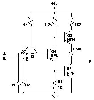
  • This is the internal circuit of a 7400 TTL NAND gate. If you leave A and B open, current flows via the 4kΩ resistor (top-left) through the base-collector junction of Q1. This makes Q4 conduct. The same happens when A and B are wired to +Vcc. For TTL gates there's therefore no difference between an open input and an input tied to +Vcc.

enter image description here

  • Not related to the problem but just in case. You're using displays with a common cathode which can be connected directly to the output of a TTL gate because the internal 125Ω resistor limits the current

$$I_{led} = \frac{3.4-2.2}{125} ≃10mA$$

2.2V is the approx. LED voltage drop and 3.4V is the typical output voltage for a TTL gate.

This is sufficient to light up most LEDs although some might be a bit dim. If you use common anode LEDs (Wired to +Vcc) you have to put an appropriate resistor in series with the LED to restrict the current.

Ambiorix
  • 1,671
  • 9
  • 8
0

Bipolar TTL inputs will (usually) appear as High (logic 1) when not connected to anything. They must be connected to ground, either directly or via the output of another chip, to be seen as Low (logic 0). This applies to the plain 74xx, 74LS, 74ALS logic families.

For the CMOS versions (74HC, 74AC), the inputs are very high impedance and must always be connected to something - either Vcc, Ground, or the outputs of other parts. They must never be left unconnected.

Peter Bennett
  • 57,014
  • 1
  • 48
  • 127