0

enter image description here

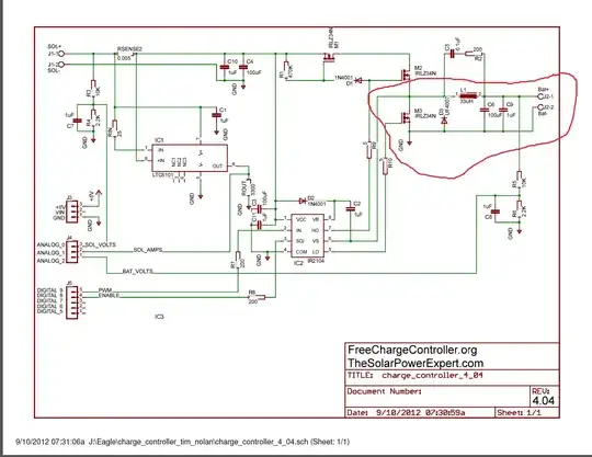
I wired one up. It's the low side assembly for:

enter image description here

I'm using a small cheap coil for my breadboard. I have been told already about the resistor 470K Ohm between the gate and source. I made sure that its there. It's color codes I looked up. When I apply 6V of power it's very nearly a short circuit. I actually saw 0.25A for a short time however it didn't last long and my mosfet is allowing about 1.87A through it. It doesn't take long for it to become burning hot to the touch with that flow and I really don't want anything to happen to my mosfet so I turned it off right now.

I've had a very difficult time getting power to stop in the drain source direction on these mosfets however the source drain direction can be stopped very easily by toggling its gate with 0V 12V.

So if that is my schematic and I tried to shut down this mosfet but it doesn't. I'm not sure what to do because if the mosfet ignites (It hasn't yet) then my schematic is not really where it's supposed to be or I am doing something wrong. (I posted a version of this question but I wasn't sure exactly if I worded everything or it was really complete. Hopefully I feel good enough about this one that it stays for a while.)

Thanks for any replies.

P.S. I did find out that the 12200Ohm resistor assembly really helps keep power down in the drain source direction on M3. The 470K resistor seems to do basically nothing in this type of configuration I have shown in my breadboard screenshot. I think my question actually has turned out to be that there is 0.44A's that flow between M3's drain and source @ 12V. So it seems that may possibly be intended to happen or perhaps not.

Eae
  • 143
  • 9
  • 1
    Your circuit makes no sense in isolation and you are probably NOT doing what you say you are. Why do you think that half a circuit will do anything useful? Where is the energy coming from? Is there a battery connected? If there is no energy from SOL+ and there is a battery connected then you are back feeding current from the battery. What do you expect this fragment of the whole circuit to do and why do you expect it? If there is more circuitry out of picture please show this on the diagram. – Russell McMahon Jan 27 '15 at 08:38
  • Actually it appears there are some pull down resistors that really help keep the current on M3 down to about 0.44ma at 12V. The resistors are shown as a tail like assembly 10K ohms and another 2200 Ohms. While I really like the idea of placing a 470K Ohm resistor between M3's gate and source it makes absolutely no difference at all in my breadboard configuration. Perhaps things will be different once the IR2104 is introduced into the circuit. – Eae Jan 27 '15 at 15:11
  • Yes of course I'm working with some fragments of the whole freechargecontroller.org circuit. As I study the fragments I hope to understand the whole circuit as whole as I learn more about it. – Eae Jan 27 '15 at 15:13

1 Answers1

0

If the mosfet does not shut down, then it might be too late already. Even tho it is said that mosfets are voltage driven, they still need a huge current on their gates to completely open and close the gate. If the gate is not opened/closed fully it will dissipate a lot of power, thus heating it up enter image description here

You will probably need a driver for that purpose. Else the mosfet just does not have enough current.

You could also put on a heat sink, but that will only mask the problem.

s3v3ns
  • 220
  • 3
  • 9
  • Yes OK. I have an IR2104. Are you saying that if I place an IR2104 in my circuit that this will be prevented from happening? Also you are saying it is too late. Have I destroyed my mosfet is that what you are saying? – Eae Jan 27 '15 at 06:30
  • You said it got very hot, and is not switching anymore, that was what you were saying. Just for safety you should have smacked a small heat sink on, until you figure everything out. You have to calculate the current needed for the gate, and then check if the driver is enough. – s3v3ns Jan 27 '15 at 06:35
  • I did have a heat sick screwed on it. I touched the heatsink because I knew it would be roasting pretty well. – Eae Jan 27 '15 at 06:36
  • Well if the size is too small, and it can not dissipate enough heat, then that will not matter. To check the mosfet itself check if there is any current through the gate resistors, when the gate is closed. If you measure something, it is dead – s3v3ns Jan 27 '15 at 06:37
  • That's what I am saying I am having a hard time with that my mosfet must be bad. It had a heatsink. I have a few test fets. – Eae Jan 27 '15 at 06:38
  • I just put a brand new mosfet in from my parts bag. It doesn't shut off either. 470K Ohm resistor is there. – Eae Jan 27 '15 at 06:41
  • There seems to be a good answer already to that question http://electronics.stackexchange.com/questions/60427/calculating-the-pulldown-resistance-for-a-given-mosfets-gate – s3v3ns Jan 27 '15 at 06:44
  • I hooked up my IR2104 and the mosfet doesn't turn off either. There must be current coming out its LO because it's reading somthing like 1.77V on my multimeter. Plugged that line into the same hole on my breadboard as the gate. – Eae Jan 27 '15 at 06:57
  • At this point i am out of time. Did you check the resistor value? 470k is pretty huge, but i am not 100% sure there since it has been a while i have worked with electronics. Try using the transistor independently? Just hook it to a PSU and put LED on Drain. – s3v3ns Jan 27 '15 at 07:08
  • Also, a multimeter is not really a thing to measure transistors with. If you could get your hands on an oscilloscope, then that would help you a lot. – s3v3ns Jan 27 '15 at 07:09
  • I have a sainsmart. It's done everything I need so far. Your right then it sounds like the scope is the tool. – Eae Jan 27 '15 at 08:11
  • I think I had my drain confused with my source pin. That was my problem I think. – Eae Jan 28 '15 at 06:12
  • That would certainly cause you problems – s3v3ns Jan 28 '15 at 06:22