What is the correct size footprint for an 0805 chip resistor? Anyone? If we all fire up our favourite PCB design softwares I bet we'll all come back with a slightly difference answer. I realise I might be wandering off topic a bit, but if helps to answer questions from other people later on then it's worth writing.
There is in existence the IPC-7351 standard. It's really boring [Check it out!] but it does give explicit naming conventions and, the reason for the answer, PCB land patterns. That said, I didn't get very far into the document before my brain shut down, so I don't have any quotable sizes from the horse's PDF. However, my PCB software (Proteus) comes with the full IPC library as well as it's own. See the following:
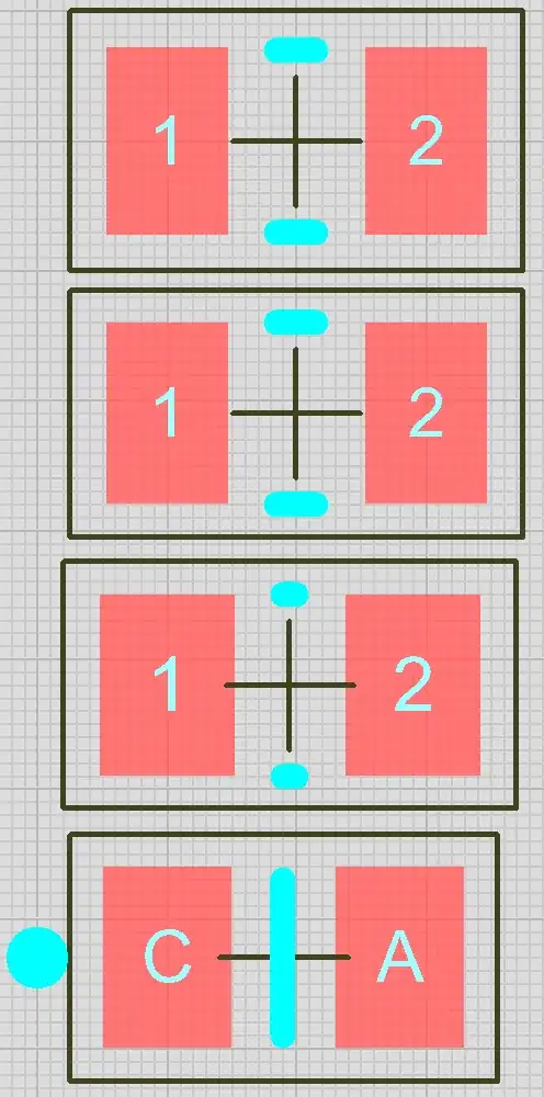
Yes, that's three footprints for 0805 chip resistors, and one for an 0805 LED. They all differ slightly, and they're all IPC. The turquoise is silk-screen graphics and the black outlines are the "occupancy" boundaries. Red is of course the pads, but I haven't shown solder mask or paste outlines. From top to bottom:
- RESC2012X50 - 0805 @ 0.5mm high. Pads 1.45 x 0.94 mm, centres 2.0mm (gap 1.06mm);
- RESC2012X60 - 0805 @ 0.6mm high. Pads 1.39 x 0.94 mm, centres 2.0mm (gap 1.06mm);
- RESC2012X70 - 0805 @ 0.7mm high. Pads 1.39 x 1.04 mm, centres 1.9mm (gap 0.86mm);
- LEDC2012X120 - 0805 @ 1.2mm high. Pads 0.99 x 0.94 mm, centres 1.8mm (gap 0.86mm).
Now have a flick through some datasheets for 0805 resistors (or any other 0805 component) from different manufacturers and see how many fit one of the above specs exactly. Very few, if any.
So what's my point? I suppose it's "do whatever's easiest for you". But excercise some common sense: What's the difference between a resistor and an LED - polarity! Yes, you can use a resistor footprint, but you'll have to mark the cathode. You could just add your own graphic if you want, but don't forget some poor bugger has to make this board and he'll have no idea what your circuit does or which way round things go unless you tell him. So long as you use common practices (marking cathode not anode) I'm sure it will be fine.
At the end of the day you should ALWAYS read the component datasheet. You might end up with a power LED that has a third pin, electrically isolated from anode and cathode, just for removing heat. If you fail to include a copper pour and some breathing space around the LED because you didn't read the instructions it might cry, and water and electricity don't mix.