I have a timer that allows me to preset times and run a motor for a predetermined amount of seconds. I need this to reverse polarity as soon as this predetermined time has expired. The timer is a digital 12 DC timer and the motor is actually a 12 volt linear actuator with built in limit switches. Thanks for the help.
Asked
Active
Viewed 7,178 times
-1
-
2It's too little information to work with. – Eugene Sh. Jan 23 '15 at 20:05
-
What is the timer? What kind of motor is it? How much power are talking about? Any others controls? I agree with Eugene Sh, we need more application information to offer any suggestions. – Adam Head Jan 23 '15 at 20:08
-
The timer is a digital 12 volt timer and the motor is actually a 12 volt DC linear actuator with built in limit switches – Mark Rasmussen Jan 23 '15 at 20:31
-
H-Bridge or DPDP relay – Jan 23 '15 at 20:37
-
thanks, but lets say that my timer turns on and applies current for 5 seconds and then turns off. My actuator will extend for the 5 seconds but will remain extended until the reverse current is applied. – Mark Rasmussen Jan 23 '15 at 20:57
3 Answers
1
To achieve this there are two options: a DPDT relay, or a H-bridge.
DPDT Relay
Here is the DPDT relay solution: (CircuitLab does not have a motor symbol, I used an inductor as the symbol instead.)
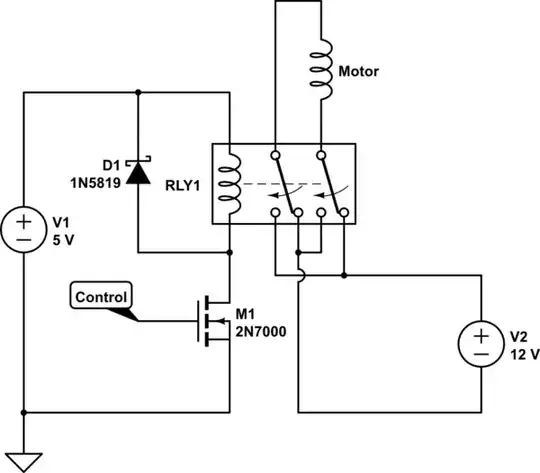
simulate this circuit – Schematic created using CircuitLab
The DPDT can drive a lot of power but it involves movng parts. H-bridge use solid state parts, hence more durable; however they tend to be more complex.
Simple push-pull H-bridge using complementary MOSFETs
Here is a example H-bridge solution if your drive voltage is between 10V and 20V:
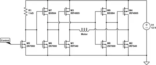
Power MOSFETs M1-M4 forms the H-bridge itself. Open-drain inverter M5/R1 is used to shift the logic levels from TTL to 12V high voltage logic. Small signal MOSFETs M6/M7 and M8/M9 are wired as CMOS inverters (look identical to a half bridge circuit) to drive the H-bridge power MOSFETs with least possible shoot-through. You can get away without one CMOS inverter circuit by driving one side of the H-bridge directly with the level shifter, and connect the gates of the
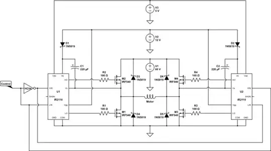
H-bridge using proper driver chip and only N-channel MOSFETs (or IGBTs)
Here is the more elaborate one, capable of switching up to several hundreds volts if you used appropriate MOSFET (or IGBT, if you are talking kilowatts), using IR2110 gate driver chip. Shown here is driving a 60V motor (alternatives like MAX15018/MAX15019 can also be used, but voltage won't get anywhere near as high as IR parts do.)
Maxthon Chan
- 2,853
- 1
- 16
- 33
0
wire the timer to a DPDT relay se tup to reverse the polarity to the motor
search motor reversing relay for details.
Jasen Слава Україні
- 31,874
- 1
- 31
- 65
0
In this article there is schematics of H-bridge for motor direction control.
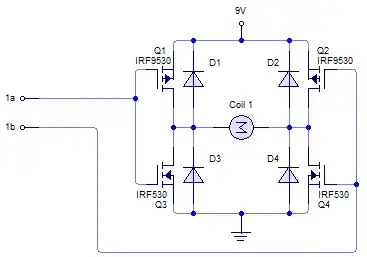
If i got it properly, you want to spin motor forward for 5 sec having a single logical 1 signal and then backward having single logical 0 signal on the same wire.
Maybe following can help together with the H-bridge:
simulate this circuit – Schematic created using CircuitLab
To avoid adding logical gates you may want to use a transistor as inverter.
Ivy Growing
- 335
- 4
- 12