0

enter image description here

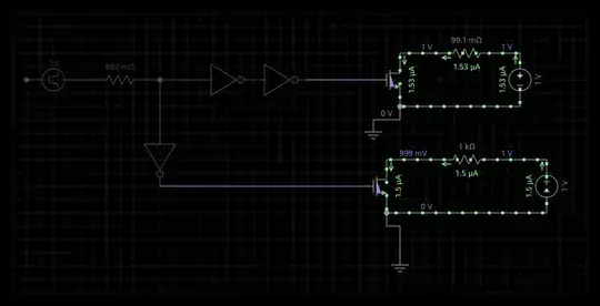
My intent is to make sure that when the top mosfet is on the bottom mosfet is off and vice versa. I'm really not sure that this accomplishes the goal. Is there some better way than this? I'm using two current sources that are configured to one second intervals. My sim doesn't look quite right when I turn it on both 1V batteries are pumping current through the mosfets.

I tried the PWM it was a little too complex for me right now but I did come up with something I though maybe works too: enter image description here

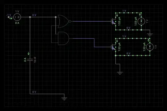
So this must be what the PWM diagram is kind of saying: enter image description here

Thank you

Eae
  • 143
  • 9

2 Answers2

1

One way could be to build your own CMOS using a PMOS and an NMOS. Look up CMOS logic or something like that to get the gist.

If you wanna do it your way, i'd hook the gates up to the same current source - one with the inverter, one without. Please note that I'm not at all familiar with the simulation environment you're using.

RYS
  • 1,018
  • 7
  • 15
1

Using an inverter is not going to work. You need to use shoot-through protection: -

enter image description here

The OR gate output needs to be inverted so an alternative is to use a NOR gate. It's going to work best when both AND and NOR/OR are schmitt trigger input types. For a quick simulation make the resistor 1k and the capacitor 10nF - this will give a "dead" area of about CR or 10us but clearly the time of the dead area is dependent on the application.

enter image description here

See also this stack exchange page.

Andy aka
  • 434,556
  • 28
  • 351
  • 777
  • Would he need shoot-through protection here since they are not configured in a bridge (high side/low side)? I don't see a path to ground through both FETs, so why the dead-time requirement? – RYS Jan 22 '15 at 08:38
  • I'm trying to put that in my simulator. Could you identify the gates. I'm guessing a bit about what they are. I see a capacitor. What is the box symbol? – Eae Jan 22 '15 at 08:53
  • An OR gate, an AND gate and a resistor. Use Schmitt trigger versions of the gates. It works because I've used it. – Andy aka Jan 22 '15 at 09:38
  • @RYS it's the same requirement as shoot thru protection - read what the OP says in his question. – Andy aka Jan 22 '15 at 09:49
  • I tired to get as close as I could to that you posted. It's there as an edit. – Eae Jan 22 '15 at 10:07
  • The output from the NOR gate feeds one mosfet and the output from the AND gate feeds the other - don't short them together. Also, where is the RC network and, don't drive it from a current source - use a voltage source. – Andy aka Jan 22 '15 at 10:08
  • Yes those were very good tips. I am trying to simulate an IR2104 but I don't understand how that IC fully works yet. It creates PWM though on the fets. – Eae Jan 22 '15 at 10:20