1

I am currently teaching my self electronics and have a question about PUTs.
I am wondering why there has to a resistor on both sides of the PUT in this circuit:

PUT Circuit

Please note that I have already read the question regarding the Make Electronics Experiment 11 and I didn't find the answer that I'm looking for.

Thanks

  • And this question/answer: http://electronics.stackexchange.com/questions/91765/programmable-unijunction-transistors?rq=1 – pjc50 Jan 21 '15 at 10:00
  • If you are teaching yourself electronics you better learn how to draw schematics. Your image is actually pretty good for a first timer but there's so much you can do to improve it. Have a look [here](http://electronics.stackexchange.com/questions/28251/rules-and-guidelines-for-drawing-good-schematics). – Vladimir Cravero Jan 21 '15 at 10:16
  • It's not actually my image. It's an image from a book that I am working through. – Michael Malek Jan 21 '15 at 11:38

1 Answers1

1

The comment link gives some of the basic circuit operations. If that does not provide your answer below is a simple written out explanation for the use of the two resistors.

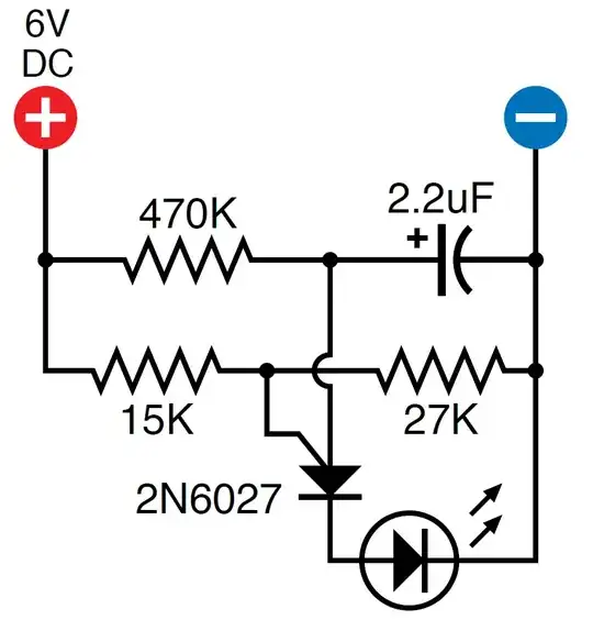
As the name implies, "Programmable Unijuntion Transistor", there needs to be a programmed voltage supplied to the Gate pin. In this circuit the two resistors (15K and 27k) provide this programmed voltage by a voltage divider action. This programmed Gate voltage could be provided in other ways without using these resistors, for example by using another voltage source.

For the circuit to operate correctly the Anode voltage needs to rise from below the programmed trigger voltage to slightly above it (about 0.65V above). When the Anode voltage is slightly above the trigger voltage the PUT will turn on HARD (conducting from Anode to Cathode).

So if only one or none of those resistors were connected (in this circuit) the Gate voltage would either be at 0v or 6v, and the slowly rising Anode voltage would not pass through the programmed trigger voltage level, it could only reach the same voltage or always be above the voltage, and the circuit would not work as expected.

Dwayne Reid
  • 23,390
  • 2
  • 35
  • 67
Nedd
  • 7,939
  • 15
  • 19
  • Thanks for that, that helps a lot. I would vote up but i don't have 15 rep yet, so I will when I do. – Michael Malek Jan 22 '15 at 05:21
  • I'm on this experiment also, I had the same question and although the explanation here is great, I believe the question is in regard to whether the resistance has to be split across the gate of the PUT or if the circuit would operate identically if the resistorder were set in series before the PUT gate or after. My understanding is that it is irrelevant which side they are on, but then why does the author split the resistance across the gate? – OnethingSimple Jul 28 '15 at 22:38
  • @OnethingSimple, perhaps by now you have your answer, but if not: The resistance is split across the gate because that configuration also splits (reduces) the voltage seen at the Gate. Placing two resistors only at one side of the Gate will not split the voltage, as in my first explanation such an arrangement would result in 0v or 6v at the Gate. – Nedd Aug 31 '15 at 03:01