1

I'm having trouble understanding the circuit in the photo below. I know that it's a gain and offset amp designed to convert 0-2.5 V range to +/-10 V range (hence it has a gain of 8 and an offset of -10 V).

But what I don't understand is how it works. It doesn't look like any of the 'basic' gain and offset circuits I've seen.

Ultimately I'd like to be able to modify the component values and Vref (currently 5 V) to take a 0-3.3 V input instead.

If anyone can shed any light I'd be most grateful!

Mystery circuit

PanicBear
  • 23
  • 2
  • 4

3 Answers3

5

To analyse the gain & offset behavior of this circuit we can ignore the 20k and 6k8 resistors on the input, since it seems that their only purpose is to provide a known bias voltage if the input is not connected.
So now the circuit looks something like:

schematic

simulate this circuit – Schematic created using CircuitLab

But with a little rearrangement we have:

schematic

simulate this circuit

which looks remarkable like a 'standard' inverting summing opamp configuration.
The 'trick' here is that what would usually be considered the inputs are now fixed reference voltages (5v & 0v), and what would usually be considered the reference is now the 0-2.5v variable input, but we can still analyse the circuit as if it were an inverting summing opamp if we take these points into consideration.

Remember that the normal rule-of-thumb for opamps with negative feedback is that the voltage on its inputs is assumed to be equal (as long as you don't exceed the capabilities of the opamp).

So, for an input of 0v what do we have?

V3 = 5v, therefore I3 = 5/13k = 385uA
V2 = 0v, therefore I2 = 0/5.6k = 0uA
Current through R2 & R3 is summed together and must be matched in R1, so:
I1 = -(I2 + I3) = -(0 + 385u) = -385uA
V1 = I1 x R1 = -385u x 27k = -10.4v The output voltage is the sum of the voltage across R1 and the voltage at the non-inverting input, so:
Vout = V1 + Vin = -10.4 + 0 = -10.4v

If we now set the input to 2.5v, the analysis becomes a little trickier (remember that the voltages at the opamp inputs are equal):
V3 = 5 - 2.5 = 2.5v
I3 = 2.5/13k = 192uA
V2 = 0 - 2.5 = -2.5v
I2 = -2.5/5k6 = -446uA
As before, urrent through R2 & R3 is summed together and must be matched in R1, so:
I1 = -(I2 + I3) = -(192u - 446u) = 254uA
V1 = I1 x R1 = 254u x 27k = 6.86v
The output voltage is still the sum of the voltage across R1 and the voltage at the non-inverting input, but now the non-inverting input is at 2.5v, so:
Vout = V1 + Vin = 6.86 + 2.5 = 9.36v

So there you have it. Its not a perfect 0-2.5 to +-10V conversion, but its pretty good considering we're not using any esoteric resistor values.

brhans
  • 14,373
  • 3
  • 34
  • 49
4

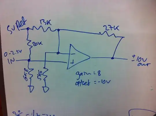
First let's remove the fluff. The 20K and 6.8K are there so that if the input becomes disconnected, the output will be approximately zero (because the effective input will be 1.268V, which is fairly close to presumed mid-scale of 1.25V.

The gain of this circuit is \$1 + \dfrac{27K}{13K || 5.6K} = +7.90\$

For the offset, assume the input is mid-scale of 1.25V and add up the currents at the inverting input.

$$V_o = 1.25V + \Big(\frac{1.25V}{5.6K} - \frac{5V - 1.25V}{13K} \Big) \cdot 27K = -0.51V$$

So the nominal transfer function is:

$$V_o = 7.90 \cdot (V_{in} - 1.25V) - 0.51V $$

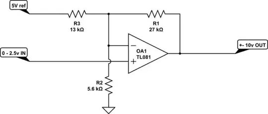
You don't necessarily need to modify the reference voltage, just the resistor values of the 13K, 27K and 5.6K, and since only the ratio matters, you really only need to modify two of them.

I'll leave the algebra to you, but as you can see it's pretty straightforward.

Edit: Okay, I scratched the algebra out for you (and future readers):

schematic

simulate this circuit – Schematic created using CircuitLab

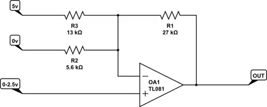
Let's assume we pick Rf to be something reasonable, Vref is given, then we want to calculate R1 and R2. We know the change in output \$\Delta\$Vo for change in input \$\Delta\$Vin and the output Vo(0) when the input is 0V.

\$R1 = -\dfrac{V_{REF} R_F}{V_O(0)}\$

\$R2 = \dfrac{R_1 R_F}{R_1 \Big[\dfrac{\Delta V_O}{\Delta V_{IN}} - 1 \Big] - R_F}\$

Plugging in the values for the above problem, Rf = 27K, \$\Delta\$Vo = 20V, \$\Delta\$Vin = 2.5V, Vref = 5.0V, Vo(0) = -10V

So,

\$R1 = \dfrac{27K}{2} = 13.5K \$

\$R2 = \dfrac{13.5 \cdot 27}{13.5 \cdot 7 - 27} = 5.4K \$

Personally, I would probably use 32.4K, 16.2K and 6.49K 1% (or better if higher accuracy was required).

You can easily plug the appropriate values in for your 3.3V problem.

Ricardo
  • 6,134
  • 19
  • 52
  • 85
Spehro Pefhany
  • 376,485
  • 21
  • 320
  • 842
3

Forget about the 20k and 6k8 - with a voltage input of 0 to 2.5 volts these resistors do nothing to explain the circuit. Then you are left with the simple case of examining two scenarios; namely the 0V in scenario and the 2.5V in scenario.

With 0V in, the inverting input will acquire 0V by virtue that the op-amp has negative feedback. So, what must the op-amp output be to produce 0V at this input?

Without the 27k feedback resistor the inverting input voltage will be: -

5V x \$\dfrac{5.6}{13 + 5.6}\$ = 1.5054 volts and have a source impedance of 5k6||13k = 3k914 kohms.

Now, apply the 27k feedback resistor and (by op-amp action and negative feedback) this voltage gets pulled to 0V.

The current that pulls it to 0V MUST equal 1.5054 volts divided by 3k914 kohms = 3.8462 mA. This current flows thru the 27k feedback resistor and this means it has a voltage across it of 10.384 volts.

In other words for 0V at the input, the op-amp output is -10.384 volts.

I'm not going to work out the 2.5V in scenario because it should be reasonably clear how to do that yourself.

Andy aka
  • 434,556
  • 28
  • 351
  • 777