4

I just completed an introductory course in digital design. During the course I designed a circuit for driving multi-color LED's with an automotive application (for a personal project). The following is what I made: LED Control Circuit

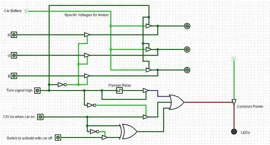
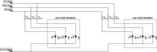
The circuit basically turns the LEDs amber and makes them blink when the turn signal comes on. After designing the circuit I decided that I wanted to control enough about 450-500 LEDs with it. The LED strips I'm using are set up for 12 Volt power sources and 450 of them would require 10 Amps.

I'm including the datasheet for the strips themselves (even though it isn't all that informative): LED Data Sheet

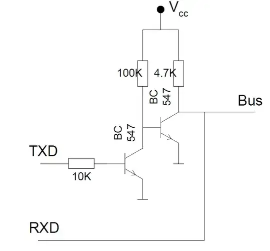
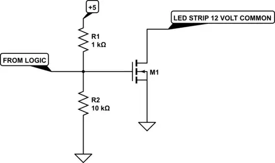
I did some research and it seemed to me that transistors were the thing to use for switching given the 12V 10A load. I should note that the control circuit will be run off of a 5V regulator and the LEDs off of a 12V regulator. At least that's the plan.

So here is the circuit after labeling where the transistors will be (labeled as "Trans."). LED Control Circuit with Transistors

Now the task of transistor selection arose and I'm struggling because I am in entirely unfamiliar territory. I need to measure the output from the turn signal before I can select those transistors, but I can select the transistor coming from that OR gate. Here is the OR gate I'm planning on using: OR Gate

I have to say I'm slightly confused that there is a negative value in the "Maximum High Level Current" category. Other than that I know I need to select an appropriate Hfe and I'm fairly sure, based on my reading, that I want an NPN transistor.

Any selection advice is very much appreciated. I realize that there are other more common ways to run LEDs like PWMs. I used combinational logic because it was the only thing I knew and it still is the only area of electronics with which I have any experience. I am willing to consider other methodology if I really should, but the functionality I'm making is fairly simple and I feel like I'm just a few components away from making it work. I'm open to all commentary, suggestions, advice, et cetera. I'm totally new to electronics so I may have to ask for further explanation of some comments, but we all have to start somewhere!

  • Learning logic as gates is good, but it's usually cheaper (fewer parts) and more flexible to implement any non-trivial logic in a microcontroller. Also, if you're using 400-500 (5 mm I'm guessing) LEDs, it might also be cheaper (cost of connecting everything and time spent doing same) to use power LEDs. – Nick T Jan 14 '15 at 23:39
  • Are there any resources to which you could direct me where I can read up on the use of microcontrollers? Also what do you mean when you say "power LEDs"? – Hebrew Hammer Jan 15 '15 at 00:10
  • An Arduino tutorial (too numerous to count) would be a good way to get started with micros. Power LEDs are generally LEDs that operate at currents over 30-50 mA, and can provide a significant amount of light. The standard 5 mm round LED is fairly limited as a light source (but it does have it's places) – Nick T Jan 15 '15 at 00:21

1 Answers1

4

For what you're doing, you're gonna have to rethink a bit. From the data sheet, it appears that each 2" segment looks like

schematic

simulate this circuit – Schematic created using CircuitLab

Since each LED should have a current-limiting resistor, you'll need 450 of them, about 500 ohms, 1/4 watt each. The resistors will need to be mounted somewhere where they have good airflow, since they will dissipate about 100 watts total. (10 amps times 12 volts is 120 watts, and it's got to go somewhere.) Just bundling them together and putting them in a hidden box is almost certain to cause Bad Problems.

Your final assembly should look something like

schematic

simulate this circuit

except extended to 150 units.

Each of the 3 drive lines needs to provide 12 volts at about 3 amps, or you can drive all 3 simultaneously with a total of 9 amps, so a 10-amp supply will probably do. There is a small chance, though, that driving all the LEDs on may draw slightly more than 10 amps, and the power supply will get unhappy. I don't have enough information to be sure. If you want to play it safe, cut back on the current a bit and use something like 560 or 620 ohm resistors. You may even want to mix values a bit to produce different drive currents, in order to get just the color you want. Experiment on a single segment before you commit to a final design. Be aware, though, that if you drive all of them the result will be (approximately) white. If you only want to produce amber light, don't turn on the blues. As a matter of fact, if you only want amber, forget about hooking up the blue leads entirely and cut your workload by 30%.

Your logic schematic is not ideal in this case, since your master drive could easily be folded into the 3 color drive signals, but I'll keep it anyways.

The master drive is relatively easy, and can be done with an NPN transistor, or actually with an NPN Darlington (you won't get 10 amps with a single stage driven by LSTTL logic). What you really want is an n-type MOSFET. Your drive circuit would look like

schematic

simulate this circuit

The MOSFET should have a current rating of 20 volts or better, and 10 amps or better. However, that is very modest as MOSFETs go.

The 3 color channel drives are a little trickier, and for these you need p-type MOSFETs. The circuit is complicated by the fact that LSTTL will not handle 12 volts on the output without Letting The Magic Smoke Out, so you need to make slightly more complicated switches.

schematic

simulate this circuit

I've shown the NPN buffer transistor as a 2N3904, but almost any small-signal NPN will do. 2N3904s are cheap and readily available. Try someplace like Jameco.

I hope this helps.

WhatRoughBeast
  • 59,978
  • 2
  • 37
  • 97
  • Thank you for the analysis! I'm going to read through it a few more times so I can come up with a semi-intelligent list of questions. I really appreciate the help! – Hebrew Hammer Jan 15 '15 at 03:10
  • @HebrewHammer - It occurs to me that it's barely possible that you won't need external resistors. Please check your LED strips. Each 2" segment will, presumably, contain 3 LEDs. Does a segment contain any other parts? Particularly, does it contain 3 small rectangular blocks? If so, those blocks are probably SMD resistors which will properly limit LED current so as to give a good white color if 12 volts is applied to all 3 inputs while the common is held to ground. – WhatRoughBeast Jan 15 '15 at 05:35
  • You are correct, there are resistors in the strip itself. I actually have a question about the master drive circuit. The red, green, and blue anodes share a common power source and each have their own ground. Diagrams I've seen of transistors being used for switching show the device being powered being connected prior to the transistor's collects, so the transistor is on the ground side. So is there even a way that I can use a transistor for switching the common power source? – Hebrew Hammer Jan 15 '15 at 07:23
  • Oho. So you can forget the part of my answer about the 450 resistors. In this case, that may mean that other parts of the data sheet are crap as well. Specifically, the part that describes the 3 color drive pins as "anode". I tell you what you need to do. Take a segment, and connect the common pin to your supply +12. Then connect the blue pin to ground and see if the blue LED lights up. If not, you've probably destroyed the blue LED. So now connect the common to ground, and connect the red pin to +12. The red LED should light. Tell me which version works. – WhatRoughBeast Jan 15 '15 at 11:51
  • Yeah that data sheet sucks. I double checked; the common line is positive and the individual colored pins are grounded. – Hebrew Hammer Jan 15 '15 at 21:34
  • So is there any way that I can switch the common positive? If not it really complicates my wiring because there is a subset of LEDs that need to turn off whenever I turn on my headlights. – Hebrew Hammer Jan 16 '15 at 18:03
  • Sure there is: use the P-type switch with a 2N3904, just as I diagrammed. However, as I also mentioned, there is no need for it. For each of the 3 channel outputs, AND them with the master ON signal. And drive the 3 resulting channels with the N-type switch. – WhatRoughBeast Jan 16 '15 at 20:28
  • Okay so I have one subset of LEDs that has to turn of when the headlights come on. Now that we have established that the color specific side is negative I'll just go ahead and switch where it says "color drive" in that last circuit with "common drive." Could you give me a run down of how everything works in that last diagram? Especially the role of the 5V source and the resistors. I'm still learning, that's for sure! Also, what is "LSTTL?" – Hebrew Hammer Jan 17 '15 at 23:45
  • The OR gate that you are planning to use is a 74LS32. This family of chips (74LSxxx) is an improved version of the original industry standard TTL logic (Transistor-Transistor Logic), which had the identifier 74xxx. So the LS version (Low-power Schottky) is generally referred to as LSTTL or 74LS. If you read the data sheet, look at the output characteristics. It doesn't source much current, but it sinks just fine. So the 1k resistor is there to provide base drive when the output is high. In this case, the collector of Q1 pulls low, and the gate of the MOSFET is too, so M1 turns on. – WhatRoughBeast Jan 18 '15 at 00:04
  • So we're talking about the last diagram above, correct? I think I understand. Can you explain what's happening across R1 and M1 again though? – Hebrew Hammer Jan 18 '15 at 04:33
  • Take a look at the 74LS32 data sheet. Maximum high output current is 0.4 mA. That's no a lot to drive the base of Q1 with. A 1k to +5 will provide 10 times that. With the collector of Q1 pulled low, there are about 11-12 volts from the gate to the source of M1. This will turn M1 on, and on hard. When turned on, the drain-source path looks like a rather small resistance, generally much less than one ohm, and this allows current to flow to the LEDs with almost no loss. – WhatRoughBeast Jan 18 '15 at 05:35
  • So basically when Q1 is on it shorts the current on the gate side of M1 and with the gate more negative than the source then M1 turns on, correct? I only read up on bipolar transistors before so I'm just reading up on FET transistors now. – Hebrew Hammer Jan 18 '15 at 05:59
  • It's better to say that, as the gate-source voltage increases, the drain-source resistance decreases. It's very similar (in concept) to the behavior of a BJT, except that the BJT works on base current, and the FET works on gate voltage. And when the MOSFET gate voltage is great enough, the drain resistance is very small - rather like a BJT in saturation when the base current is large enough. – WhatRoughBeast Jan 18 '15 at 15:19
  • That makes sense! One more thing that I thought of: Since I'm regulating the voltage to each of the three colors on the negative side in order to make amber, I need to come up with the best resistor to down regulate the voltage. I need to run the red at 12V (easy, that's what will be feeding the common positive), the green at 4V (so I have to lose 8V and be able to handle up to 3A basically), and blue will be off. So what is the best way for me to step down the voltage to the green? This seems like a simple question, but I figured it best to ask someone experienced nonetheless. – Hebrew Hammer Jan 19 '15 at 19:04
  • @HebrewHammer - If you're running the green at 4 volts, no way are you drawing 3 amps. You'll need to measure the current the green actually draws, then multiply by 150 to get the actual current you need for the whole array. Then use V = I x R to calculate the resistance. Use P = V x I (where V is 8 volts, and I is the total green current) to figure how big a resistor you need. I'd expect a few watts. The good news is that, since each LED has its own resistor, you only need a single external resistor for the whole bunch. And don't forget a heat sink/cooling fan for the resistor. Smoke is bad. – WhatRoughBeast Jan 19 '15 at 19:17
  • I'll figure out what the actual amperage will be. Thank you for all the help, I really appreciate it! I'm going to try to finish my parts list and I'll probably post up the part numbers just to make sure I got it right. – Hebrew Hammer Jan 20 '15 at 02:22
  • Do you think I could use this N Channel MOSFET for the color drive lines? https://www.jameco.com/webapp/wcs/stores/servlet/Product_10001_10001_1559885_-1 – Hebrew Hammer Jan 21 '15 at 22:21