8

This may seem like a topic beaten to death, but bear with me.. this is an apparently ignored wrinkle. Over the past several weeks I've been designing various circuits to protect a LiPO cell from under-voltage, if the user of my device carelessly leaves it on. Now I know you can buy protection circuits ready made, but most of them start cutting the current when the LiPO voltage gets to around 2.5V. If you really want to protect a LiPO cell from damage, 3.0V is a much better discharge point to call it quits. At this point I thought I had a few good solutions, but I may be wrong... dead wrong!

I don't know about you, but if I accidentally leave something ON, and its something I don't use every day, then it might be ON for days... maybe weeks or months. I've come to realize that just about any scheme to stop battery draw when the voltage is too low is NOT going to drop the current to ZERO. Even the best MOSFET based circuits are going to have leakage current, and a good control circuit may increase it more. So how low is low enough?

I suppose its somewhat related to the capacity of the cell. Obviously if my cutoff circuit limits cell current to less than 1 uA, that's going to prevent a 10000maH cell from damage for a good long time. But what about a 200mAH cell? Would a cutoff to 1uA offer "reasonable" protection or am I just kidding myself? What about 1/10 of that (100nA)? the lower the circuit leakage, the more expensive the design. So how low is low enough?

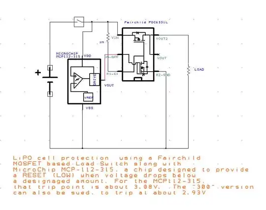
Addendum... Here is a circuit I'm intending to try. If it works as I'm hoping, it will will reduce residual current to about 1uA when the cell voltage reaches about 3V. There are only 3 parts here, a Load switch made by Fairchild (FDC6331L) does all the grunt work of cleanly switching my load, while a Microchip part ( MCP112-315 or MCP112-300m) "trips" at about 3V, to control the load switch. The total cost of this circuit is about $1, and the low part count is due to the multiple parts inside each IC. This is still unproven but I'm hopeful. But if it works as planned, time and experimentation will tell how long it actually protects a little 200mAh cell in actual use, when the user leaves the load ON.

enter image description here

Randy
  • 3,205
  • 3
  • 21
  • 38
  • 1
    At 1 uA, 200mAh lasts you, uh, 25 years.Not long enough? –  Jan 11 '15 at 01:19
  • 2
    @BrianDrummond - Either you don't understand LipO cells, or you don't understand my question. 200mAh means at it should provide power to the circuit for the expected time, at the expected voltage. After that the cell voltage starts dropping very quickly, because it does not have any useful life left. If you keep draining a LiPO and it drops much below 3V, its not going to take a normal charge again. I'm trying to PROTECT the battery, and I'm trying to find out from those who have explored this how much protection is adequate. – Randy Jan 11 '15 at 01:54
  • 1
    A relay will give you zero leakage, and no voltage drop. Are you going to calculate the low voltage over several samples, because voltage can drop in a high current due to internal resistance. – sparky Al Jan 11 '15 at 02:43
  • I would guess that a good metric would be to compare the circuit draw with the self-discharge current of the cell, but no guess is going to be as good as looking at the detailed application information from a the manufacturer (hopefully you're using a top-tier maker who supplies such information). – Spehro Pefhany Jan 11 '15 at 03:25
  • I have seen protection circuits that cut off at 3V. Typical protection circuits protect against under voltage discharge, over voltage charge, over current charge, and over current discharge. Are your really planning to try to do all that and have smaller standby current after the under-voltage-discharge function has kicked in? Anyway, I think you should limit the standby current to as low as possible. I believe the existing protection circuits are down around 10 uA. – user57037 Jan 11 '15 at 04:10
  • A single deep discharge will not usually permanently damage a lithium cell. I have had to test lithium cells, and one of the tests is to defeat the protection circuit, discharge to zero volts and then recharge and measure capacity. The charger does need to use a small current until the voltage recovers to something over 3V. – user57037 Jan 11 '15 at 04:12
  • By the way, it is a little bit arrogant of you to think that industry standard solutions would all be stupid and wrong in their selection of cutoff voltage. Just sayin, and no offense meant. ;-) – user57037 Jan 11 '15 at 04:14
  • @Sparky - I considered an OMRON latching relay. No a bad idea, but they are bulky, and I fear I'd need a need a reliable discharge from a large capacitor, to ensure enough residual power to toggle it with a low battery. A non latch would draw too much current – Randy Jan 11 '15 at 15:18
  • 2
    @mkeith - I'm pretty sure I have a two part solution that will take me down to about 1uA. Still, I guess there is no way to know for sure how effective that would be if left running a month. As far as arrogance, I assure you my post is the result of actual experience of many DIY'ers who have dealt with these cells, including yours truly. The first tiem I actually ruined a cell and found it wouldn't take a full charge anymore, its voltage was 2.6. And I am using a very reliable and widely used MAX1555 charge management chip. It may be you had some better cells and mine were "el-cheapos" :-) – Randy Jan 11 '15 at 15:24
  • 1uA is better than off-the-shelf. I can see how repeatedly discharging to 2.6 might damage a cell, and I can see how storing the cell for a long time in a severely discharged state would be bad. But I am still having trouble believing that a single discharge to 2.6V would permanently reduce capacity. At the system level, the protection circuit is not supposed to be the only thing that stops discharge. The system should shut down at 3 or 3.3V or something, which should prompt the user to recharge. Maybe some people are relying 100% on the protection circuit to end discharge? – user57037 Jan 11 '15 at 18:34
  • The max1555 is a battery charger IC, not a cell protection controller. Take a look at the offerings from Seiko: http://www.sii-ic.com/en/semicon/products/power-management-ic/lithium-ion-battery-protection-ic/ – user57037 Jan 11 '15 at 18:44
  • @Randy See addition to my answer where I discuss a zero power when off circuit. – Russell McMahon Jan 11 '15 at 22:05
  • This is a very old thread, but I thought I'd revisit to mention that at least for my application with 200mAh liPo cells, my circuit has been 100% successful. This is part of a product I developed for musicians, of which I am one. I not only use it everyday, but as predicted I have left it on way too many times. After a year now, the circuit reliably "trips" when inadvertently left on, and after this "abuse", the protected cell's usable time has not measurably decreased when brought back to full charge. So for what its worth, 1uA max after a 200mAh cell reaches 3V is a very good solution – Randy Jan 07 '17 at 19:38

4 Answers4

5

Amongst other things I design solar charged lights.
I want customers to be able to put a "dead" light in a dark place for a long while without destroying the battery.

My approach is to reduce off current to so close to zero as to not matter and then deal with battery self discharge issues.

1 uA = 8.8 mAh/year.
Scale that for time and discharge rate as desired.
8.8 mAh is 1% of the capacity of an 880 mAh cell.
You can decide what reserve you wish to allocate to this task for a given battery.

An "off" MOSFET has near infinite resistance. Even a fully off bipolar transistor passes only a tiny fraction of a uA at the sort of voltages typically concerned. The problem is usually with current in dividers used to sense battery or other voltages. One megohm passes 1 uA/volt. As you increase divider resistance you need increasingly low leakage and bias currents and offset voltages. You can buy specialist parts with very low current consumption indeed - but they are usually a significant cost in low cost designs or completely beyond consideration. Instead, when Vbattery has got as low as it is going to be used at for any purpose, I turn the dividers off - usually with a high side bipolar transistor. It is easy to get a current so close to zero as to be irrelevant compared with other factors. When charging next occurs I re-enable the low voltage cutoff circuitry with charging energy and the process starts again. If recharge is not enough to bring the battery level back up to the absolute minimum level it again "goes back to sleep" as soon as charging stops. This arrangement takes a few more parts than a purpose built low current divider IC,but costs far less,and ultimately performs as well or better than anything you can buy.


Added:

The circuit below from this question Solar charging circuit question does what you want. In this case it's self contained so turn on and off of the left hand divider by T1 is powered by the solar panel and does not load the battery. The on/off circuitry at right here uses a TL431 (under 3 cents in China in volume) but could be anything that works for you. T1 off draws ~= zero current. Cathode current for a turned off TL431 is < 0.050uA (50 nanoamp) worst case.

This circuit is not for LiIon but would work as well with changed resistor values. At elevated temperatures the reverse leakage current of the Schottky blocking diode may become the dominant quiescent load - a pleasant problem to have :-).Here PCB area and manufacturing costs would be the largest cost - components that manage the actual zero current shut down in volume ex China are in the 5-10 cent range.

Control circuit current when on is not usually a major issue as solar energy is available, but if you want to minimise current, using a TLV431 rather than a TL431 reduces minimum on cathode current when in-regulation to under 100 uA.

enter image description here

Russell McMahon
  • 147,325
  • 18
  • 210
  • 386
  • Wouldn't mind seeing some of your circuits! You've definitely nailed the issue of quality vs cost. Consider the simplest (and maybe sloppiest) protection would just be a single MOSFET with a VGS threshold of 3V in series with the load. The protection would be near perfect current wise, but the transition from normal to marginal voltage on the load would be ugly as sin. A good comparator with some hysteresis makes for a nice sharp cutoff, at the expense of a few uA. Turning off the comparator is essentially tuning off the turn off circuit :-), which is intriguing but has to add some cost. – Randy Jan 11 '15 at 17:12
  • I'm having a little trouble understanding that circuit. Where does the battery connect, and where does the load connect. – Randy Jan 12 '15 at 05:55
  • @Randy This is similar in end result but different in exact application to your MCP112... IC. Your IC drives a high side switch that removes power including its own. This circuit is a lhs is a solar battery charger monitor with panel at left PVIN and battery at right 3V. BUT the battery OVERCHARGE divide R15 R14 loads the battery and without Q1 would drain the battery below minimum safe level. So the divider is removed by T1. Here the divider is enabled by U1 T1 only when there is solar voltage present but in low battery situations the divider can remove itself with T1. I can show you a ... – Russell McMahon Jan 12 '15 at 07:39
  • ... circuit that does exactly what you want using the same general principle in "a few days time". Low voltage divider turns itself off. Solar energy wakes it up again. Rushing madly at present. Going to hospital tomorrow for relatively minor spinal surgery which should help and just may not(very low chance) . If you don't hear back from me ... :-). Ask again in 3 or 4 days. IF I get a chance before leaving tomorrow '' dig cct out but probably not. – Russell McMahon Jan 12 '15 at 07:42
  • Thanks again, and I'm sure I speak for everyone in wishing you the best possible outcome. – Randy Jan 12 '15 at 14:28
5

For the benefit of anyone following or discovering this thread, and who contributed, all of whom I very much appreciate, I'd like to follow up with a successful bench test on this circuit I formerly said I was going to try. It may be slightly overkill for my modest current needs, but the whole circuit only cost about $1 to make, has very few parts, is good to a few amperes if you needed it (I only need 20mA), and bottom line it works VERY well! With the part variations shown, it will cut of power very close to 3.0V, a very good voltage to ensure protection of a LiPO cell even if the circuit is left on for a long time. And when it goes into shutdown, I measure the continued current draw at 0.8uA. That, to me, is VERY good protection. In my case with a 200mAh Lipo cell, I've estimated the user could forget the circuit was left on for possibly months, depending mostly on the self discharge rate of the cell, before the cell voltage wold drop to a point where damage is eminent. The only change I'm making is that the 1M pullup resistor would be better kept down to 10K - 100K, to offer a little less sensitivity to any ambient EMI fields.

Thanks again, everyone who participated. This is now one less problem I need to worry about.

Successful Lipo Cell protection

Randy
  • 3,205
  • 3
  • 21
  • 38
3

Okay, according to this web page, the protection circuit typically draws somewhat more than the internal self-discharge rate (1-2%/month for the battery, and another 3%/month for the protection circuit). The LM3641 draws typically about 1uA when low voltage protection is active.

enter image description here

Credit to batteryuniversity.com for this image:

enter image description here

But really, the best information should come from application notes or other information provided by your battery supplier.

Spehro Pefhany
  • 376,485
  • 21
  • 320
  • 842
  • Thanks. Thats a good starting point for sure. Unfortunately when you look for bargain cells you often won't get such detailed info. What is add about this info however is that for the lithium ion-case (at least Lithium Polymere chemistry) , a partially discharged state of about 3.3V is recommended for long term storage, leading me to think the don't self discharge at all? – Randy Jan 11 '15 at 15:30
  • @Randy You could try to find information from reputable makers and ass-u-me that the behavior is similar. All cells self-discharge, some faster than others. – Spehro Pefhany Jan 11 '15 at 15:50
  • So if a 200maH cell lost 2% (4maH) over a month, a month is 720hours, and 4/720 is .005mA, or 5 uA of continuous self discharge (or did I screw up the math?). So if a protection circuit in that case would be expected to consume another 3% (or 7.5uA continuous), and my circuit is only consuming about 1uA, I guess I should stop whining and realize that's pretty decent. Granted there may only be a few % useful life by the time the cell gets down to 3V. But if it meant a user could accidentally leave the unit on for a month or two without actual cell damage, I think that's pretty respectable, no? – Randy Jan 13 '15 at 02:20
  • @Randy Sounds respectable. I think 1uA is about the level where I'd stop worrying about it. – Spehro Pefhany Jan 13 '15 at 02:23
1

Use a Seiko S-8211C Series battery protection IC. A range of over and under-voltage thresholds are available. Some of the individual parts have a shutdown function which reduces power consumption to below 1uA in the case that the cell Voltage falls below the low threshold. A possible specific part number is S-8211CAZ-I6T1x.

I feel very confident that one of the Seiko parts will meet your requirements, and Seiko has a lot of experience in this area (these IC's are widely used in commercial products shipping millions of units).

user57037
  • 28,915
  • 1
  • 28
  • 81
  • Thanks. I've seen a few ICs like this, and have no doubt they do an adequate job at the mechanics of the protection functions. It is a few more parts than I wanted to use and also, unless I've misread, these ICs consume about 2uA in the protect/shutdown state. I already think I have some solutions with less parts that will reduce current to that amount or a little lower. But the real thrust of my question was to better understand how well a reduction to 1 or 2 uA will protect a LiPO cell, or at least for how long, and whether or not I can do better than 1 or 2 uA. – Randy Jan 12 '15 at 05:49
  • You can do it with fewer parts? I would like to see that. There is one tiny IC, a dual FET, one cap and two resistors. Also, once the under-voltage threshold is tripped, the power consumed from the battery is a fraction of a uA. The IC provides a total protection package, including fast short circuit cutoff and over-voltage cutoff. These ship in the millions built-in to Lithium ion batteries. They are so small you can't even see them unless you take the pack apart. I think you should at least take the time to look into it. – user57037 Jan 12 '15 at 06:12
  • I will check into it and try to sample one or two. About I think I'll opt for the bigger SOT-23 5-pin model, a little easier on my aging eyes and less than 100% steady hands ;-) I rechecked the data sheet and you're right... its 0.2uA not 2uA as I thought (those aging eyes ;-) The part count isn't so bad. If I had my wish list though, it would be nice if the internal FETs had a little more drive, so low power apps like mine wouldn't need external FETS. I posted a circuit I'm working on, but at best it drops to 1uA after low voltage trip. – Randy Jan 12 '15 at 14:48