1

Other answers here show a common way to allow a microcontroller to cause a contact closure (button press) within another device in an isolated fashion: use an optoisolator.

I have the reverse problem. I've got a distant unpowered button, and I want to know when it is pressed. I want to know this without risk of damaging my µC due to badness \$\gg V_{DD}\$ on the long wires running back to that button. If you want a mental model of the application, think of it as an electronic doorbell.

I already know how to sense the remote button press in an unprotected fashion:

unprotected pushbutton input

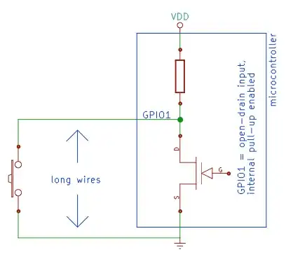
I also know about the standard method of microcontroller input protection. (Zeners, GDTs, TVSes, MOVs, current-limiting resistors...) I was just hoping to be able to buy a 2- or 3- terminal blob with some combination of those components arranged, qualified, and quantified. I even dared hope that I could find a gang of N of them in a "firewall IC" for under $10. (4 ≤ N ≤ 10) I want the effect of going to the littelfuse.com homepage and saying, "Yes, I'll take all of that, and can you tie it up and put a bow on it for me, please?" Littelfuse seems to prefer that I buy a pile of discrete parts instead.

An optoisolator won't work here because it requires that I either power the remote end with a separate isolated power supply or give up some isolation by powering the LED side of the isolator from the microcontroller's supply.

I want it to work with just a raw contact closure. If there's any voltage coming from the button, it's either an application error that I wish to protect against (e.g. active sender rather than a dumb button) or badness per above.

The Infineon ISO1I813T is the closest thing I've found so far:

Infineon ISO1I813T application schematic

The problem is how many external components it requires. With the same number of components, I think I can probably come close to its effect with the standard method. The only thing I lose is isolation, and I'm not sure I really need that. All I'm certain I need is protection.

As a provisional goal, let's try to make it withstand at least an indirectly-coupled lightning strike. Somewhere between that and EMP-proof would be nice. :)

Warren Young
  • 3,742
  • 24
  • 30

4 Answers4

2

Maybe not low enough component count, but what about this?

schematic

simulate this circuit – Schematic created using CircuitLab

It's isolated, within the limits of the transformers, and requires no power at the switch. The only real complications are generating and sensing the sine wave.

markt
  • 4,936
  • 2
  • 15
  • 13
  • @WarrenYoung Look again. No power is required on the remote side. The MCU both generates the sine wave, and reads the received sine wave. – markt Jan 10 '15 at 12:19
  • So you put V1 in there just as a simulation aid? Shouldn't it be over on the other side, for clarity? – Warren Young Jan 10 '15 at 12:20
  • @WarrenYoung No, V1 isn't a simulation aid. V1 is the stimulus put into the system by the MCU. If the switch is closed, the stimulus can pass through both transformers and be received by the MCU; if the switch is open, then the stimulus goes nowhere. – markt Jan 10 '15 at 12:21
  • Oh, you're saying the µC is on *both* sides of this schematic. A PWM pin on one side, and the GPIO on the other, for example. And that's why you need two transformers: because you also have to isolate the two µC pins from *each other*. – Warren Young Jan 10 '15 at 12:23
  • @WarrenYoung You're getting it, but the two transformers isolate the _switch_ from both MCU pins. – markt Jan 10 '15 at 12:24
  • 1
    Two transformers is overkill. It can be done with just one. But while a transformer provides good protection against common-mode transients, it does nothing at all to suppress differential-mode transients. – Dave Tweed Jan 10 '15 at 13:22
2

One class of devices that may be worth a look at are the integrated TVS devices used for USB protection. They include a TVS and current limit resistor but might be a bit light-on for lightning protection if that may be an issue. One example is the Semtech STF203 series available from Digikey at reasonable low-volume prices.

PeterJ
  • 17,131
  • 37
  • 56
  • 91
1

Easiest thing to do is just give the button its own power supply, assuming the total time it spends pressed is minutes over the course of years. Coin cell + series resistor to drive an optoisolator.

Next easiest thing to do is a tiny AC-coupled system like markt's answer; could probably be done with one transformer and current sensing.

pjc50
  • 46,540
  • 4
  • 64
  • 126
0

I'm going to add another silly thought I had last night that should meet your requirements for both isolation and protection, although I acknowledge that there are a few issues with it.

Replace your long wire with two optical fibres, one each for Tx and Rx. At the button end of the link, orient the two fibres such that Tx points into Rx over a small air gap (lenses are probably advisable). Replace the electrical components of the button with a blade that pushes into the air gab and obstructs the optical path when the button is pressed.

I have in my head a picture of the fibres entering a button block in parallel (rather than end to end), with the block containing both the button mechanicals and prisms and/or lenses for the optics. Unfortunately I have no mechanical/optical drawing tools to turn the mental image into a screen image.

An alternative: a single fibre, with the button blade replaced with a mirror. Push the button and the signal is reflected back down the fibre.

It may sound a little left field but it's about as electrically isolated as you can get and the button end at least is EMP-proof...

markt
  • 4,936
  • 2
  • 15
  • 13