4

I am recreating the Adafruit Powerboost 500c Circuit, but I want to reduce the LED's I need down to one. It has four LED's to represent the following signals, next to which I put the desired behavior for my circuit:

  • BLUE - Power (I don't care about this signal)
  • RED - Low Battery - The LED should be lit when the battery is Low.
  • ORANGE - Charging - The LED should be lit when the battery is charging.
  • GREEN - Fully Charged - The LED should be unlit when the battery is charged.

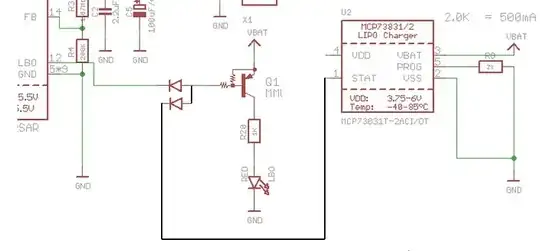
I am removing the BLUE LED and R5. I am removing the GREEN LED and R7. I want to light a single LED if either the input to the RED LED or the input to the ORANGE LED is high. I wasn't sure if just hooking both inputs to an LED without other circuitry was a good idea so I googled "OR Gate circuit" and discovered three possibilities: a Diode OR Gate, a transistor OR Gate, and an OR Gate IC. If any of these is the best choice, which is it and why? If none is best, then what is?

Note: I asked this question before in an attempt to ask in a "generic as to be helpful to others" way and I was told that I needed to provide more details (among other comments on my poor circuit design that, while helpful, didn't answer my question). I provide more details and the thread was too old to warrant attention and, consquently, I did not get the answer I was looking for. I would delete my old question if I could, as I clearly presented it poorly.

Nate
  • 173
  • 1
  • 8
  • I think a diode-'OR' should work when you insert one diode at base side of Q1 and connect the other diode to U2/STAT. Do be aware of diode polarity, because of the inverted inputs and the inverting transistor. – jippie Jan 09 '15 at 06:08
  • Why would you ever want *fewer* LEDs? – Connor Wolf Jan 09 '15 at 06:32
  • LED's are great but if you have four lights for charging, one for wifi, one for bluetooth, ... it gets a little difficult to keep track. Just google Nintendo 3DS LED colors and you will see some jokes/complaints about a similar issue. That aside, most mobile devices only have one power LED, sometimes it is multi-color, but there is usually only one LED. – Nate Jan 09 '15 at 20:53

1 Answers1

4

A diode OR using 2 diodes as shown will work.
Either drive line can pull Q1 base low without affecting the other.

Technically it's a diode AND with +ve logic but as our activating signals are active-low i't a diode OR with negative logic.
It could also be seen as a DTL = "Diode transistor logic" AND (or OR) gate.
Long ago you could buy AND gate ICs and this is almost exactly what was inside.
So all your choices are ~~~~~~= the same :-).

This is "best" because it works, is quick and easy and only requires 2 diodes.
Diodes can be about anything.
Usual small diode is 1N4148 but a 1N400x or almost anything else will work.

In1 / In2 / Out

0 0 0
0 1 0
1 0 0
1 1 1

enter image description here

Russell McMahon
  • 147,325
  • 18
  • 210
  • 386