2

I made a school boy error in buying the BS170. It doesn't produce enough continuous current to power my leds. They're bicolour and can only be wired in parallel hence I would need at least 2 amps!

Since I can't return them I was wondering can I just get some transistors to amplify the current up to 2.5 amps. Also would it have a knock on effect on the resistors am using? enter image description here 
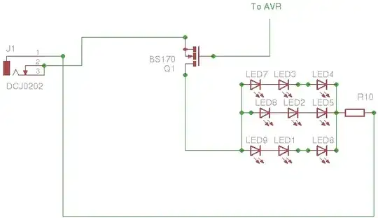
I have 20 copies of this circuit on strip board. Some of the leds are grouped together and switched by one mosfet hence the 2amp

Sorry the led is actually supplied by 5v regulator which isn't on the diagram

stevenvh
  • 145,145
  • 21
  • 455
  • 667
Ageis
  • 3,311
  • 13
  • 44
  • 67
  • What is the LED spec? (I and V) and the value of R10 and Volt in to DCJ0202? – Max Kielland May 30 '11 at 12:55
  • 2.5 v 30ma sorry i meant 10 ohms. 19volts dc – Ageis May 30 '11 at 12:56
  • 6
    Placing LEDs in parallel is a Bad Idea. You risk that LEDs in one branch light more brightly than the others. Replace R10 with a resistor for each branch. – stevenvh May 30 '11 at 13:33
  • so you're saying each row of three resistors shud have it's own resistor? – Ageis May 30 '11 at 13:36
  • 1
    also, you know that with the limiting resistors suitably adjusted, an unregulated 7.5V (etc) works just as well for lighting LED's as a regulated 5V, right? with currents like these, that can cut down the load to your regulator, and thereby the heating, considerably. – JustJeff May 30 '11 at 13:58
  • Three LEDs in series can't be lit by 5 V, unless their individual drop is less than 1.6 V. http://www.oksolar.com/led/led_color_chart.htm If the LED drop is 2.5 V, and you have a 19 V supply, then use that. You can get 7 in series lit with 19 V. – endolith May 30 '11 at 14:21
  • 2
    @Ageis - Yes, each row should have its own resistor (Accidentally deleted my previous comment) – stevenvh May 30 '11 at 14:42

5 Answers5

4

You don't need to "amplify the current". It will flow automagically when you switch the LEDs on. The thing is that you need a switch (MOSFET or BJT) which can stand the 2A.
A power MOSFET would be ideal, since they're available with very low \$R_{DS}(on)\$, so they won't get very hot. You can do a parametric search on this Fairchild page. For example the FDN339AN and FDN359BN have low \$R_{DS}(on)\$.
An other option is to use a darlington transistor. They're not ideal though: \$V_{CEsat}\$ is rather high, often 2V, so when you run 2A through them you need some cooling.

stevenvh
  • 145,145
  • 21
  • 455
  • 667
2

I'm not really sure of what you mean with "Amplify" the current. You can't "create" more current from nowhere. All your current will be drawn from your power supply through your transistor, divide into 3 paths through your LEDs and then through your transistor.

A serial path has the same current, so your 3 LED's should together be \$ U = 2.5 \times 3 = 7.5V\$ drop and \$I = 0.03A\$. Then you have 3 of these paths in parallel creating 3 paths of current, \$0.03A\$ each \$= 0.03A \times 3 = 0.09A\$ through the resistor.

Your resistor is there to limit the current through your LEDs. If you Drive with 19v and have a drop of 7.5V over the LEDs you need to put the remaining V over R10 \$= 19-7.5 = 11.5V\$.

The resistance should be \$R = \frac{11.5V}{0.09A} = 127.8\Omega\$ and \$P = 11.5V \times 0.09A = 1.035W\$. Still the current through BS170 and R10 are the same, 90mA.

You could either switch your transistor to a bigger one \$(20 \times 90mA = 1.8A)\$ or have the same pin (from your AVR) driving multiple transistor, each driving their own circuits.

I usually use biopolar transistors such as BD435 that can drive 4A Collector to Emitter. Just put a 1K resistor in series to the base and it will operate as a switch. You could dimm all your LEDs by feeding it with a PWM signal. But in this case the transistor must be placed close to ground so the AVR signal (5V) are above the transistors threshold (BE) 0.7V.

(I might have forgot something in the formulas, but the principle is the same).

Adam Lawrence
  • 32,921
  • 3
  • 58
  • 110
Max Kielland
  • 647
  • 2
  • 11
  • 24
  • 1
    The BD435 has an \$H_{FE}\$ of only 50 minimum, so you would need 40 mA base current for \$I_{C}\$ = 2A. That's probably too much to drive directly, so you'll have to create a Darlington with an extra transistor. – stevenvh Jun 04 '11 at 15:36
2

you're schematic is wrong.

the right way is shown here:

http://www.electronics-tutorials.ws/transistor/tran_7.html

under: An example of using the MOSFET as a switch

A suitable MOSFET would be a logic level MOSFET in your case because you only have 5V to drive the gate. Something like an FDN337N will work up to 2.2A. The FDN339AN can be used for currents as large as 3A. However, those things come a SOT23 package but they can be mounted on the back of strip-board with some care.

Regards

Hendrik
  • 282
  • 1
  • 5
  • By the way, the FDN337N or FDN339AN will not get hot at all. The RDS-on of the FDN339AN is 0.035 Ohm @4.5V gate drive. with a drain current of 2A it will get 35°C above room temperature if you don't take the increase in RDS-on with increasing temperature into account. – Hendrik Jun 01 '11 at 00:46
1

Transistors don't "produce" current, they allow current to flow. Your particular transistor is only rated for 500mA, so you are right that it is inappropriate for this circuit. You need a transistor rated for at least 3A. However, that's only part of the rating. No transistor is a perfect switch, so there will be some voltage drop accross it. The transistor will dissipate Watts equal to that voltage drop times the 3A current.

If the transistor is a FET (which would be appropriate in this case), it will be rated for some Rdson value. This means that when fully on the FET looks like a resistor with a value of Rdson Ohms. The power dissipated in a resistor as a function of the current thru it is:

Watts = Amps**2 * Ohms

For example, if the FET is rated for 100 mOhms Rdson, then at 3A it could dissipate up to 900 mW. That's a lot more than a SOT-23 case can handle, for example. Even a TO-220 standing up from the board in free air will get noticably hot, but probably stay within specs. You need to consider this power dissipation issue, since it will probably be the limiting factor. The easiest way to deal with it is to get a FET with low Rdson, or use one FET for each LED string.

You really should at least use a separate current limiting resistor per LED string anyway. Each string will have a little different voltage at the same current, so they won't share the current equally. Worse yet, the voltage will go down with increased temperature. So one string will get more current, which will make it warmer, which decreases its voltage drop, which makes it get a larger share of the current, which makes it even warmer ...

Something else doesn't add up. You show 3 LEDs in series but also say the power is coming from a 5V supply. That means each LED can't drop more than 5V / 3 = 1.67V, which is very low for any normal LED and doesn't leave any voltage for the resistor to keep the current at least somewhat predictable. This contradiction leads to other questions. Are you really sure these LED strings require 1A each? Unless this is a lighting application that is rather unlikely.

Olin Lathrop
  • 310,974
  • 36
  • 428
  • 915
  • If you want to encourage users to write 30 mA instead of 0.03 A ([this answer](http://electronics.stackexchange.com/questions/14852/how-do-i-calculate-the-resistor-value-for-a-simple-led-circuit/15000#15000)), you may as well use quantities instead of units in quantity relationships: \$power = current^{2} * resistance\$ – stevenvh Jun 04 '11 at 15:31
0

As mentioned already in previous answers. You cannot "amplify" current. However if you would like to increase the capacity of your circuit to allow sourcing or as i would recommend sinking the current for your LEDs you may use multiple MOSFETs in parallel. However choosing the correct MOSFET should allow for adequate current flow.
The first consideration for your circuit is whether your MOSET is N or P channel. The second consideration is whether or not it needs to be isolated from the "logic level" or source and sink signals to and from the arduino. There are a number of ways to do so a small transistor or optical coupling device.

For reference and design of your new schematic I suggest studying RC Electronic Speed Controllers (ESC). These devices are designed to produce 3 phase alternating current. This requires the use of at least 6 MOSFETs and are designed for high current applications and controlled my MCU's typically AVR devices. In the link listed is a schematic to the Mikrocopter ESC version 2.0 you could use the design from this page and an N channel MOSFET with resistor to power your LED's. To do so simply ignore the the P channel MOSPET that provides the positive half of the third phase and use the N channel MOSFET of your choice to sink the current of your LED's also no logic level coupling is needed in this solution.

http://www.mikrokopter.de/ucwiki/en/BrushlessCtrl

In addition I do not understand why the LED's cannot be wired in series. From your schematic it seems the are wired series parallel. I would maximize voltage consumption before current.
Also keep in mind field effect transistors are not linear regulators.

http://en.wikipedia.org/wiki/MOSFET

Good Luck !

P.S. Steuer_c- will be connected to the arduino. Phase C or the drain of your MOSFET to the cathode of your LEDs. The value of the resistor between the arduino and your MOSFET is subject to change depending on the MOSFET you choose. Remember the flow of electrons is opposite the flow of current.

stevenvh
  • 145,145
  • 21
  • 455
  • 667
minimer
  • 197
  • 10