7

I've been creating a MIDI Thru box project and was trying to avoid having so many resistors. Points A-G may (or may not) have a load connected to them. Are these equivalent, or do I really need to include a resistor on each branch?

Here's the circuit image

http://a.yfrog.com/img611/175/4rfk.png

Is the current/resistance/voltage equivalent from the DC supply to each lettered branch in each circuit? More importantly, can anyone explain (or provide a link that explains) how you came to the conclusion? I'm a developer just starting to learn electronics.

I've gotten mixed responses on twitter, and someone mentioned asking here.

Kevin Vermeer
  • 19,989
  • 8
  • 57
  • 102
Pete
  • 173
  • 8
  • Not directly related to your question but a design consideration: failure of R in circuit B means failure for all ports. If too many devices cause the resistor to fail, all ports will become useless. – Erik Noren May 27 '11 at 17:08
  • Why are you trying to avoid the resistors? Ease of construction? Space? Cost? There are packages that contain lots of resistors tied to one common pin to save space. http://www.interfacebus.com/resistor-network-schematic-bused-resistors-sip.html – endolith May 27 '11 at 18:37
  • I was trying to simplify the circuit. In the end, it's not a big deal, but the additional resistors do complicate the trace routing. – Pete May 28 '11 at 05:40

5 Answers5

5

Suppose points A through G in circuit A are connected to ground. Then there's a current 5 V / 220 Ohm = 23 mA through every resistor for a total of 7 * 23 mA = 159 mA. In circuit B there's only one 23 mA current. They're not equivalent.
Also, in circuit A the resistance between any two of the inputs is 440 Ohm, in circuit B this is 0 Ohm.

stevenvh
  • 145,145
  • 21
  • 455
  • 667
4

They are not equivalent.

Imagine placing a 1K resistor on point A to ground. Also place a 10K resistor on point B to ground.

In Circuit A, a 220 resistor is in series with the 1K. There is a separate 220 resistor in series with the 10K.

In Circuit B, the 1K and 10K would be in parallel.

Robert Deml
  • 3,232
  • 6
  • 29
  • 27
  • While true, is that a situation he will likely encounter? Won't the MIDI endpoints be reasonably similar in their resistive load especially given the small value of R? – Erik Noren May 27 '11 at 17:01
  • I'm not sure I quite understand. Why would the 10k and 1k be parallel in Circuit B but not in A? I'm sure this is a complete noob question, but there's some bit of theory here that hasn't clicked yet. – Pete May 27 '11 at 17:05
  • Pete, in circuit A you'd end up (effectively) with a 1220 Ohm resistor in parallel with 10220 Ohm resistor for an final resistance of 1090 Ohms. In circuit B you'd end up with 1000 and 10000 Ohm resistors in parallel, both in series with a 220 Ohm resistor for a final resistance of 1130 Ohms. – Scott Bussinger May 27 '11 at 17:41
  • In MIDI, isn't the load just an LED, not resistive? Like http://dernulleffekt.wolfgang-spahn.de/midi.html – endolith May 27 '11 at 17:57
  • @Erik: Even if all the loads were exactly the same 10K resistors, when they're combined in parallel it will be 1.4K, which will drop the voltage more than if each 220R only saw 10K. – endolith May 27 '11 at 17:57
4

Pete, I don't know much about MIDI circuitry, but it appears that the outputs are simple open collector circuits with pull up resistors and inputs are opto-isolators. If that's not reasonably accurate, then somebody please correct me.

Given that understanding and assuming that the power supply you're using is adequately large so we can assume it'd capable of providing as much current as you want, then you could think of the two circuit options like this:

Circuit A is treating each of the inputs A-G independently and what's happening on input A isn't affecting what's happening on input B.

Circuit B is shorting all of the inputs A-G together and just happening to supply a bit of extra current to the mix. Anything happening on Input A is totally messing with what's happening on Input B. If Input A is trying to be +5 v and Input B is trying to be 0v, then you've got the outputs of two other boxes fighting each other and neither is working correctly any more.

  • `neither is working correctly any more.` Not only that, but there could be a high chance that the chips there will let their magic blue smoke go. – AndrejaKo May 27 '11 at 18:00
  • A through G are inputs or outputs? – endolith May 27 '11 at 18:07
  • 1
    A through G are outputs. Pin 4 in a MIDI jack. – Pete May 27 '11 at 18:25
  • 1
    @Pete: Then this answer doesn't apply, since it's talking about shorting a bunch of outputs together, like if A and B were inputs and connected to different sources and one tried to send high while the other sent low. – endolith May 27 '11 at 18:50
  • @Pete: Often, inputs are shown on the left and outputs on the right, so that signal flow is from left to right. Of course the circuit works the same no matter how it's drawn, but it helps readability and preventing misinterpretations like this. http://opencircuitdesign.com/xcircuit/goodschem/goodschem.html – endolith May 27 '11 at 19:01
  • 2
    endolith is right, if A-G are all outputs, then my comments don't make sense. But there must be more circuitry not shown here then because otherwise it's going to be really boring output (a steady +5 volts). – Scott Bussinger May 27 '11 at 22:21
  • @endolith: If outputs are on the right and inputs are on the left, wouldn't signal-flow before from right-to-left? – BlueRaja - Danny Pflughoeft May 27 '11 at 23:42
  • @BlueRaja: If the inputs are on the left, and the outputs are on the right, then the signal is flowing from left to right. It comes in from external circuits on the left, is processed by the device in the middle, and is output to external devices on the right. Not sure what you're imagining. – endolith May 28 '11 at 00:17
  • @endolith: Oh I see, I was confusing the device's outputs with components which output a signal. Thanks for clearing that up. – BlueRaja - Danny Pflughoeft May 28 '11 at 00:34
  • 1
    @endolith etc. Sorry, yes, the points on the left are all outputs. – Pete May 28 '11 at 05:42
3

This is like a fan-out circuit to drive multiple MIDI inputs?

If I understand MIDI correctly, each of these outputs feeds directly into an LED, not a resistive load, like this:

enter image description here

If the LEDs have a drop of 2 V, then circuit A would be applying (5 V - 2 V)/220 Ω into each LED = 14 mA.

Circuit B, on the other hand, puts all the LEDs in parallel, so they each get 1/7th of that current = 2 mA. This could prevent them from lighting enough to register as signals. Also, any variation in the voltage of the LEDs (if one optocoupler uses an IR LED and the others use green LEDs, for instance) would allow the lowest voltage LED to hog all the current and prevent the others from lighting at all.

endolith
  • 28,494
  • 23
  • 117
  • 181
  • Yes. Obviously the real circuit is more complex, but the +5V (not signal, just power) is shown in my diagram. The points A-G are pin 4 on a MIDI Thru (out) jack. When implemented properly, an optocoupler is used, as you show. There are no guarantees of that, but for the most part, that's a reasonable assumption. Also as shown in your diagram, the receiving end also has a 220ohm resistor, when implemented correctly. – Pete May 27 '11 at 18:20
  • @Pete: The resistor at the receiving end would eliminate the current-hogging problem, but not the low-current problem. And you can't guarantee the resistors are there either? And you can't guarantee they didn't implement the inputs without optocouplers? Definitely should stick with a resistor on each output, as designed. – endolith May 27 '11 at 18:36
1

Yes. They could be equivalent. No, they aren't equivalent. It depends. <g>

(to clarify, they circuits aren't really equivalent - my response above is mostly in response to the implied question of, "can I replace this part of a more complex circuit and get equivalent results)

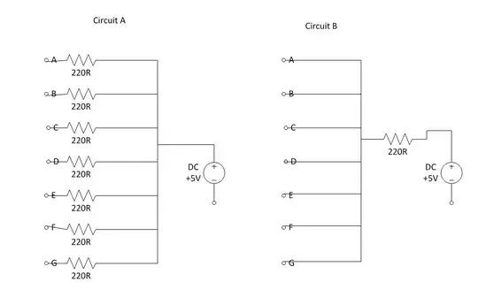
I think a more interesting question is, in your particular circuit, would replacing the 5 resistors hanging off the 5v line with one resistor cause any problems?

(it's been a really long time since I've done any kind of circuit analysis - and only in school - so I might have missed something below)

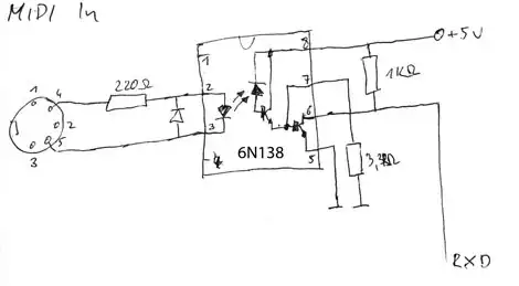
If you look at the standard MIDI circuit (I used this as an example) and compare it against your circuit diagram, you can see why it's designed the way it is. It appears as though the resistor is there to limit current. The MIDI output circuit has (2) 220 resistors while the input has just 1. When pin 5 of the output goes low current can flow across the opto-isolator from the +5 line on pin 4 (and passes through (3) 220 ohm resistors in series Ra, Rb, Rc in the diagram). If you short any of the lines the various resistors will keep too much current from flowing.

If you take a look at the datasheet for the inverter or the opto-isolator even if you removed the 220 ohm resistor on the +5v side of things you still be within tolerance of the parts (not flow too much current) (but don't do that - a short could cook parts in that case).

So it looks like you could use just 1 resistor in your particular circuit so far.

What about power? How much power will this resistor need to handle?

In the original circuit you've got 5 resistors so if you replace them with a single one this resistor will need to handle 5X the amount of power. Does it matter? Power is P = I * V, and V = 5. To calculate "I", first calculate the total circuit resistance, 220 (5v side) + 220 (pin 5 of the output) + 220 on the input side, so 5 / 660 (I'm going to ignore the 1.2/1.4 voltage drop of the opto; let's assume it shorted) = 7.5mA. P = 5 * 7.5mA = 37mW. 5 circuits * 37mW = 189mW. So it's less than a 1/4 of a watt even with all of them active (although that's not providing a ton of headroom, I'd probably use a 1/2 watt to be safe).

So it looks like you could replace it with a single resistor.

One other consideration - what happens if that 1 resistor fails? If it fails as an open circuit, all 5 ports would stop working. In the original circuit only a single port would be dead. If it shorted, the other resistors in the circuit would probably keep anything from cooking (so you're still safe there), although if you have multiple shorts (between equipment) you'd still cook things, as mentioned above.

  • 1
    For more fun, it hadn't even occurred to me (as some of the other posts are pointing out) to consider "what if" someone else decided to remove pieces of their circuit to help control costs/parts count/board space. – Paul Mrozowski May 27 '11 at 18:41