5

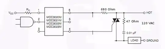
I keep frying resistors in the following optocoupler and triac snubber circuit, and I'm not sure whether to attribute this to bad design, or to faulty components.

  • There are no observable sparks at turn-on, but the 680-ohm resistor burns out within seconds.
  • I'm using 1/4W through-hole resistors.
  • The power triac gate triggers at <= 35mA.
  • The load is a ~50W fan that runs on mains power.

Switcher circuit

If my understanding is correct, the steady-state (ON) power dissipation of the 680-ohm resistor should be less than 0.1W.

If you agree that my design is reasonable, then what component do you suspect is faulty, and why?

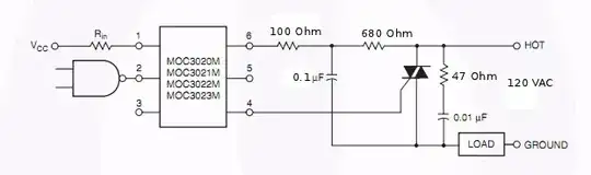
I also tried the following circuit, but again, the 680-ohm resistor smoked when I put the optocoupler in the ON state: enter image description here

Isaac Sutherland
  • 771
  • 2
  • 8
  • 17
  • Calculations for the resistor dissipation? – Leon Heller May 26 '11 at 10:52
  • 2
    try sizing the 680 ohm as though you were planning on putting it and the 0.1uF cap in series across the full line voltage; by my calculation the 680 ohm would dissipate a tad more than 1.3W .. so a 2W or better part should take it. – JustJeff May 26 '11 at 11:03

4 Answers4

4

I suggest you read TI app note SLUP100, "Snubber Design" by Philip C. Todd for some good background on snubber design.

When the triac is on, the dissipation through the snubbers will be low since they are 'shorted' by the triac.

When the triac is off, load current is going to try and flow through both of your snubber circuits, and the resistors are going to see power dissipation.

Are you absolutely sure that the triac is firing each cycle?

Adam Lawrence
  • 32,921
  • 3
  • 58
  • 110
  • I'm fairly sure my triac was fried. I wired up a simple circuit with only a 100-ohm resistor between hot and the gate (always on) and the resistor roasted, then tried it again with a fresh triac and it worked. – Isaac Sutherland May 30 '11 at 13:04
3

The fact that your resistor blew a few seconds (versus milliseconds) after turn on, is a clue that you are exceeding wattage by at least a factor of 2, but probably less than a factor of 10.

The path through the triac should not affect the 680 Ohm R.

The path through the 0.1uF cap is not nearly high enough current to fry the 680 (assuming 60Hz power and a good cap).

If the IC is sinking more than 19 mA through pin 6 at any time (I did not check the specs on this device) then you are exceeding the 1/4 W on your 680. If the chip can sink much more 'I' than 19mA (like the 35 mA you mentioned... is that going through pin 6?), then I think we found your problem: Pick a resistor with a Power Rating (PR) and value (R) that satisfies PR > Power=(I^2)R.

If the triac triggers at 35ma through pin 6, then size R larger than (0.035^2)(680) = 0.833 Watts. I'd select a 680 Ohm, 1W.

Vintage
  • 802
  • 4
  • 4
1

Put a much higher wattage resistor in that position and measure the current through it. You will find that your calculation is wrong.

If you read the data sheet you will see that the resistor in question and the 0.1 uF capacitor aren't necessarily needed (they constitute a snubber for the coupler). Try removing them.

Leon Heller
  • 38,774
  • 2
  • 60
  • 96
  • I just tried again with the 100-ohm resistor and 100nF capacitor removed. The same thing happened -- the 680-ohm resistor fried as soon as I put the optocoupler in the ON state. The load doesn't seem to get any power. It smells as though my triac is fried -- lots of power going into the gate without triggering the triac. – Isaac Sutherland May 26 '11 at 17:32
  • And yes, my calculations were indeed wrong -- I wasn't even thinking about the current that would flow into the 100nF capacitor through the 680-ohm resistor. But the resulting power dissipation in the OFF state wasn't sufficient to make the resistor smoke (at least not initially). It's the ON state current that is worrisome. – Isaac Sutherland May 26 '11 at 17:35
  • Read what I wrote, again. I said remove the resistor in question and the 0.1 uF capacitor, not the 100R and 100nF! – Leon Heller May 26 '11 at 17:49
  • I removed the 100-ohm instead of the 680-ohm resistor (I removed the 0.1uF capacitor). Sorry for not doing exactly as you said ... Even so, I was expecting (in this modified circuit) the OFF state power dissipation of the 680-ohm resistor to be 0W and the ON state power dissipation to be approx. (0.035)*(VT)/2*asin(VT/120)/Pi (in watts) where VT is the voltage across the 680-ohm resistor required to trigger the power triac (VT = 0.035*680). That works out to 0.026 watts. ... Do you agree I probably have a fried triac? – Isaac Sutherland May 26 '11 at 18:23
1

Did you check the wiring to the triac? It sounds like you wired it the wrong way. Also, you should use a carbon composite resistor for the the resistor in the snubber across the triac. This type of resistor will be able to handle the voltage surges it will experience. A wire wound resistor might spark between it's own turns and a metal film resistor will just die over time.

Hendrik
  • 282
  • 1
  • 5
  • It's possible ... I only learned that the gate needs to be connected through a resistor to the terminal 2 node (connecting it to the terminal 1 node) after asking this question, so maybe my test was invalid. I threw out the triac in question, so it's hard to check it now. Would wiring up the gate to the wrong terminal end up in high power dissipation in the on state? – Isaac Sutherland Jun 02 '11 at 17:32