5

I'm attempting to emulate the modulation and demodulation of a PAL video frame in software, but I'm having trouble understanding how the AM (luma) and QAM (UV) components of the signal are separated during the demodulation process.

Background:

The software I'm writing takes an RGB bitmap, translates it to Y'UV using the BT.601 standard, generates (modulates) a signal as a series of samples, then saves those samples to a wave file. Those samples can then be loaded back in and demodulated back into a bitmap, with the H-sync pulses honoured against the H-pos ramp generator as an old CRT TV would do, and finally translated back into an RGB bitmap.

There are two motivations behind this project: first, to create some cool looking analog fuzz in software; and second, to better understand the TV standards and basic modulation / demodulation techniques in a domain (software) where I am more comfortable.

What I've got so far:

The code performs the modulation fine, and when the result is viewed in Audacity (with a sample rate faked at 1/1000th the real frequency) it shows a signal that I recognise to be a series of PAL picture lines. The full process works if I put it in black-and-white mode, thus omitting the QAM signal from the modulation step and leaving only the amplitude modulated luma channel. I've also tested the QAM modulation and demodulation code against a simple audio file, and it works great. The only bit I haven't got working is the image demodulation with both the AM luma and QAM colour components included.

The confusion:

Given a pure untouched QAM signal, it seems relatively trivial to demodulate the signal back to its original composite signals, by multiplying with the carrier sine and its cosine individually:

$$I_t = s_t \cos(2\pi f_c t)$$ $$Q_t = s_t \sin(2\pi f_c t)$$

The two components are then low-passed at the carrier frequency to remove high-frequency terms. This seems to work great, and as I noted above my implementation of QAM demodulation works just fine.

Similarly, I can implement simple AM demodulation, even when the signal is accompanied by other signals in separate parts of the frequency domain - it's just a case of high-pass and/or low-pass until you've got the bit you want.

However, from what I can see, the QAM modulated UV component is added to the base AM luma signal, with both parts overlapping in the frequency domain, as the following diagram from Wikipedia appears to show:
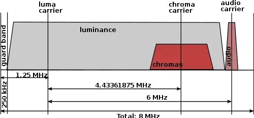
At this point I'm a little stumped. It doesn't look like I can low-pass to get the AM luma signal due to the overlap, and I can't see how I'd subtract the QAM signal from the underlying AM.

What am I missing? What are the logical steps that should be taken to separate the luma and UV components?

Polynomial
  • 10,562
  • 5
  • 47
  • 88
  • Definitely simple filters deteriorates vertical definition. A technique to avoide this is described in a patent http://www.google.com/patents/US3707596 – GR Tech Jan 06 '15 at 05:56

3 Answers3

3

There's a trick that is used in NTSC that I believe also applies to PAL.

If you look at the fine detail of the spectrum of the luminance signal, you find that most of the energy is concentrated at multiples of the horizontal sweep frequency, with relatively little energy in between these peaks (this energy represents diagonal edges in the image, which are relatively rare). There is a similar pattern in the details of the chrominance signal. Therefore, the color subcarrier frequency was carefully chosen to place the peaks of its power spectrum between the peaks of the luminance spectrum.

The filters that can separate this information into two separate streams again are called "complementary comb filters". You create a comb filter for the luminance signal by delaying it by one horizontal line period and adding it to the original signal. You then subtract this filtered signal from the original signal to get the complement signal, which contains primarily the chrominance signal (which you subsequently bandpass filter to the appropriate range of frequencies).

Dave Tweed
  • 168,369
  • 17
  • 228
  • 393
  • You know, this phenomenon was explained to me a very long time ago, before I really understood how the standards worked, and I forgot about it completely. Looking at some of the PAL comb filter designs, I can see that they're doing exactly what you explained: line delay into an addition. I'll give this implementation a go and see what I get. – Polynomial Jan 06 '15 at 14:11
1

Bandpass filter around colour subcarrier to eliminate (most of) the luma signal before the chroma decoder, and the matching notch filter in the luma channel to keep crawly bit patterns out of the luma channel.

What's probably missing in your ENcoder so far is a notch filter to eliminate (or rather, reduce) luma information around the colour subcarrier. Choice of filter bandwidths is up to you, according to how you rate the importance of chroma bandwidth, the loss of luma bandwidth, and cross contamination.

Anyone who watched the Six O'Clock News in the 1970s (on BBC1) will tell you that the overlap was real, and even with the best filtering there was some cross-contamination of chroma into the luma channel and, rather more obviously, from fine luma detail into the chroma channel.

More specifically, they will recall the distracting rainbows dancing across Kenneth Kendall's body as he moved, thanks to the black and white checked tweed jacket he insisted on wearing!

When digital filtering became practical, better and cleaner PAL coders became possible but the problem simply cannot be completely eliminated.

And in some contexts it has positive side effects; it has proved possible (but difficult) to recover colour from a monochrome film copy of a broadcast!

0

A notch filter that dips in and takes out the color info? Check this app note out it goes more into y/c separation techniques. You could just low pass high pass but with loss of detail.

The book video demystified is a good resource too, you can find a free copy online.

Some Hardware Guy
  • 15,815
  • 1
  • 31
  • 44
  • Surely the notch filter would also include all the HF components of the luminance, thus ruining the quality of the image greatly? Conversely, the luminance signal would also be distorted by the chroma section, or missing its HF portion if I band-stopped that too. Interesting app note though - looks like I maybe need a comb filter? – Polynomial Jan 06 '15 at 01:58
  • Yes, check the app note though, they go into comb filtering and then adaptive comb filtering to solve that. – Some Hardware Guy Jan 06 '15 at 02:01
  • I read the app note, but I can't really see how to construct a comb filter that separates the signals. Their use makes sense, but I don't know how to build one for my specific needs - what frequency(s) should I be targeting, and how do I construct a filter that does target that frequency? I'm also unsure on which type of comb filter I need, as there appear to be a few different ones. – Polynomial Jan 06 '15 at 08:44