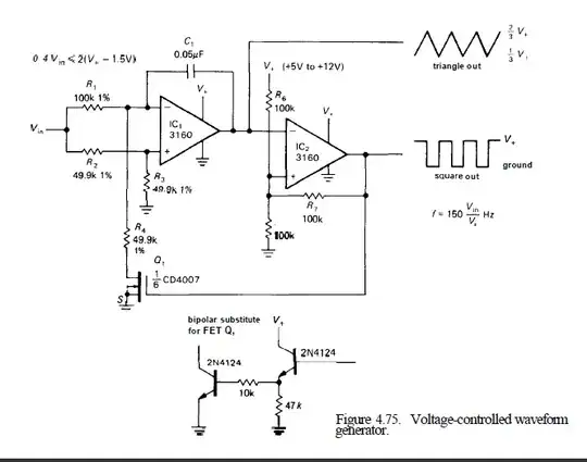
This is with reference to a circuit i saw in The Art of Electronics.The authors claim that IC1 is an integrator and that the circuit ensures that a current of magnitude |Vin|/(200k) constantly flows through the capacitor.They further explained that only the direction of current changes at regular intervals determined by the Schmitt trigger IC2.
I suspected that the opamp IC1 is a comparator(no negative feedback).So I simulated the circuit with LT Spice (with Vin =6 Volts) giving me the following results.
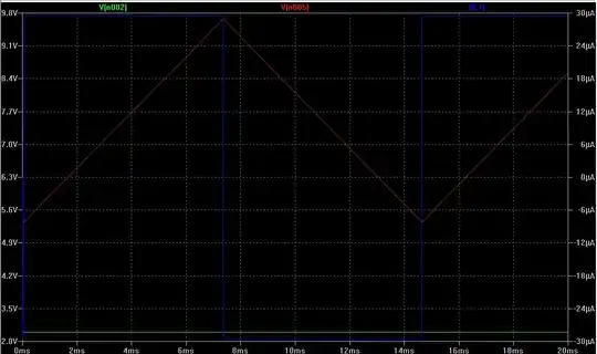
The waveform in green is the voltage at inverting terminal of opamp IC1.The waveform in red is the voltage at the output of IC1 and the blue waveform is the current through capacitor C1.The simulation proved that the authors were indeed right!! The inverting input was held constant at 3 Volts(for Vin=6 Volts).
This meant that the capacitor somehow completes the feedback loop providing negative feedback and thus ensuring that voltage at non inverting terminal = voltage at inverting terminal. I came to terms with the fact that the capacitor 'completes' the feedback loop.I guessed that since the capacitor conducts throughout the time period ,it must always behave like a varying resistor completing the feedback loop.
But then I had trouble explaining why a capacitor doesn't complete the feedback loop in an astable multivibrator circuit.
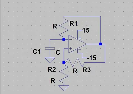
The above circuit can definitely be explained by considering the opamp as a comparator switching between Saturation voltages at fixed thresholds.Simply said- the capacitor doesn't complete the feedback loop.
So to summarize my question -why does the capacitor complete the feedback loop in the Voltage Controlled Oscillator circuit but not in an Astable Multivibrator???