3

First off, I'm new to electronics.

Can anyone please explain how differential input reduces noise?

My understanding (please correct me if I'm wrong): noise usually gets added to the original signal hence increasing it's magnitude, so now if I want to amplify this signal (without the noise) I should provide the same signal to both inputs of a differential amplifier. Since the noise is already added to the original and is present at both terminals, the CMRR should reject signals common to both terminals including noise since it is present in both signals and the output voltage will be zero. Then how should I amplify the signal?

Also even if we have two different input signals, one with noise and one without noise, but same as the other (except noise content), then CMRR should make sure it only amplifies the difference between the two, which is noise. Why would we want to amplify the noise and reject the original signal?

widdalightsout
  • 41
  • 1
  • 1
  • 2

3 Answers3

3

Differential amplifiers (ideally) eliminate common-mode noise. Real differential amplifiers always have some small mismatch between the positive and negative inputs, so CMRR is given as a figure of merit.

Any generic op amp can be configured as a differential amplifier (using discrete external resistors), but a chip marketed as a differential amplifier is optimized to handle differential signals. Among other things, the resistor networks will be internal, and will be better matched over temperature than you would get with discrete resistors.

You don't actually provide the same signal to both inputs. A differential signal is different than a single-ended signal. A single-ended signal uses ground as a reference, but differential signals include their own reference.

If you think of using a handheld DMM to measure a signal voltage, usually you'd connect the negative lead of the DMM to the system ground. That's single-ended measurement, because you only need to place the positive lead to make the measurement. Now imagine you want to measure just the voltage dropped across a pullup resistor under some condition, you move the negative lead to one end of the resistor and the positive lead to the other end of the resistor. That's a differential measurement.

Some signal sources need to be differential. Take a look at a Wien Bridge for example, this is an arrangement commonly used in strain gauge load cells and other transducers.

Proper connection routing is important to help ensure that any injected noise is mainly common-mode noise. A typical printed circuit board connection would route the sensitive signal as a differential pair, with the positive and negative PCB routes running alongside each other. When using insulated wires instead of a PCB layout, like in a lab bench test setup, a twisted pair of wires can be used.

If noise is injected into one route and not the other, that isn't common-mode noise, and such a setup would not get the benefit of the differential amplifier's common-mode noise rejection.

What you suggest about using a differential amplifier to amplify a noise signal, is related to a control loop configuration called feedforward ( see http://en.wikipedia.org/wiki/Feed_forward_(control) ), treating the noise source itself as a signal to correct another stage.

MarkU
  • 14,413
  • 1
  • 34
  • 53
  • It is interesting to see what is the role of the twisted pair in this arrangement... – Circuit fantasist Dec 31 '14 at 10:51
  • thanks, this really helped. One last thing, I can safely say this is how a differential signal would look like,[link](http://i57.tinypic.com/24zgfvo.png) now If input to a differential amplifier is a a signal with common mode noise, the output would be signal without common mode noise or it should be entirely zero as Ad(v2-v1) [this v2 and v1 is common mode noise or entire signal voltage? ] .. what should be the output? thanks – widdalightsout Dec 31 '14 at 11:18
  • @Circuitfantasist I have actually asked [that very question](http://electronics.stackexchange.com/questions/80195/twisted-pair-wires-effect-on-common-mode-noise) myself. There is only one answer, but may provide some help. – Adam Head Dec 31 '14 at 14:45
  • @Adam Head, I have added another explanation of the twisted pair idea (very similar to the Scott Seidman's explanation and to yours). A brilliant idea... – Circuit fantasist Dec 31 '14 at 17:23
  • when i see a DOPA it says voltage noise is 2nV/rtHZ, so this noise is inherent with opamp and cannot be eliminated despite being a differential ?? if DOPAs are such low noisy why dont i see them in pV/rtHZ ?? you mean it only eliminates the noise in common with inputs but the opamp noise cannot eliminated ? how can we reduce the opamps noise ? – kakeh May 14 '16 at 04:54
  • @kakeh Please post that as a new question, so everyone can answer... ok to link to this question, but in short *thermal noise* is distinct from *common-mode noise*. I think what you're trying to ask is **how to minimize the effect of thermal noise in a differential opamp circuit.** That's a whole other topic that deserves some attention. – MarkU May 14 '16 at 18:04
  • no its not thermal noise i am speaking on, but the voltage / current noise of the opamp itself, can they be eliminated using diffopa's – kakeh May 16 '16 at 02:46
  • @kakeh I don't know. That's why I suggested you post this new question *as a new question*, so that the other people can see. As it is now you're only asking me, and I don't know the answer. – MarkU May 16 '16 at 09:46
2

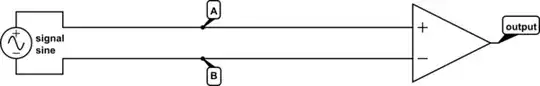
Say you have some signal, connected by a pair of wires, to a differential amplifier:

schematic

simulate this circuit – Schematic created using CircuitLab

How might we describe the current in these wires? One way is simply to measure the current on A, and the current on B.

Alternately, but equivalently, we can think of a common-mode current and a differential mode current. Differential mode currents are those where a current on A is accompanied by an equal but opposite current on B. For example, if there is 1mA on A, and -1mA on B, that is a purely differential mode current of 2mA.

Common-mode currents are currents that are equal on each conductor. If there is 1mA on A, and also 1mA on B, that is a purely common-mode current of 1mA.

In practice, the current at any time will be a mix of the two. If we measure 4mA on A, and 2mA on B, then the differential-mode current is 2mA (the difference of the two) and the common-mode current is 3mA (the average of the two). Formally:

$$ I_\text{differential} = I_A - I_B \\ I_\text{common} = \frac{I_A + I_B}{2} $$

Why is this useful? The signal, as I've drawn it, can only create differential currents on A and B. It has no connection to anything else, so by Kirchoff's laws any current entering on the A side must be exiting on the B side.

But what about noise? Noise can couple into this system through mutual inductance or capacitance. If the impedance to A and B are equal from the perspective of the noise source, then whatever currents result from the noise will be equal in A and B, and thus, common-mode. This is a really important point: for a differential measurement to get any benefit of noise reduction, the impedances of the two differential lines must be equal. Any impedance imbalance allows noise to couple to the differential mode, adding noise to the signal. Equal impedances also assures that equal currents make equal voltages, at which point it becomes irrelevant if your amplifier is a voltage or current amplifier: a common-mode current makes a common-mode voltage so it will get rejected either way.

A differential amplifier ideally amplifies only the differential mode. In practice the common mode isn't rejected entirely, the CMRR, or common-mode rejection ratio, will specify the extent to which this is true in the datasheet. Even for commodity opamps, this can be quite high. For example, TL072 specifies a minimum CMRR of 75dB. Thus, to the extent that we can maintain impedance balance on all the connections (which is actually the hard part), noise will be common-mode, and thus attenuated by 75dB relative to the signal.

Phil Frost
  • 56,804
  • 17
  • 141
  • 262
  • Very good explanation... but it would benefit many if used voltages instead currents... "Differential amplifier" usually means "differential voltage amplifier" having high input impedance... – Circuit fantasist Dec 31 '14 at 17:32
  • @Circuitfantasist as long as the impedances are equal, it doesn't matter. See edits. – Phil Frost Jan 01 '15 at 01:15
  • The only problem of your explanation is that, in this "balanced line" arrangement, there are no currents flowing. First, currents do not flow due to the high input impedance of the differential amplifier. But even if it is low, currents still will not flow, because the two currents are equal and opposite... and cancel each other... Your explanation would be reliable if this differential amplifier had current inputs... and the two currents entered them... and subtracted somehow inside the amplifier... – Circuit fantasist Jan 01 '15 at 09:19
  • @Circuitfantasist huh? Firstly, currents *do* flow, because although you may have an amplifier with a *high* input impedance, you will never find one with an *infinite* input impedance. Secondly, where are equal and opposite currents cancelling each other? They are not in the same wire: one is in A, the other is in B. This is a situation that happens all the time, like on every properly operating transmission line, or on the Vcc and ground connections of your power supply. – Phil Frost Jan 01 '15 at 13:32
0

@widdalightsout, your thoughts about the noise rejection are completely correct.

About your final question... a possible sensible reason can be just to investigate the very noise... Happy New Year!

@Phil Frost, you made me begin thinking about how can be two equal currents subtracted (cancelled)...

Here we have a loop... and it is not correct to talk about subtracting currents in a loop... and voltages - by a node. Conversely, we can subtract currents by a node (current summer)... and voltages - by a loop (voltage summer)...

When subtracting two equal currents by a node, the one current enters and the other - exits the node... and the output is zero current... and a voltage that can be amplified by a humble single-ended amplifier (a typical example is the summing point of the op-amp inverting amplifier). Here the both currents flow in the same direction towards the differential amplifier.

In a node, the both currents will be subtracted but they still exist; similarly, in a loop, the both voltages will be cancelled... but they still exist in the loop... In your explanation, both the currents have disappeared, and there is no current flowing in the line...

If the currents flow in different wires, then we have to assume that this differential amplifier has low single-ended input resistances (between each input and ground) and the currents pass through them to ground. But in this case not the very currents are cancelled; they are converted into (the single-ended) voltages that are subtracted in the amp input loop. So, "currents will flow, because although you may have an amplifier with a high input impedance, you will never find one with an infinite input impedance" but if you mean the single-ended (not differential) input impedance... and even in this case, they will be caused by induced voltages (EMI). Then why not talk directly about voltages instead of currents?

Circuit fantasist
  • 13,593
  • 1
  • 17
  • 48