Dave Tweed's answer is excellent on the facts (and so I upvoted it). Since this is basically a newbie question that is covered/answered in most intro electronics textbooks, there is one addendum perhaps worth making: how to figure it out (or convince yourself)... using SPICE!
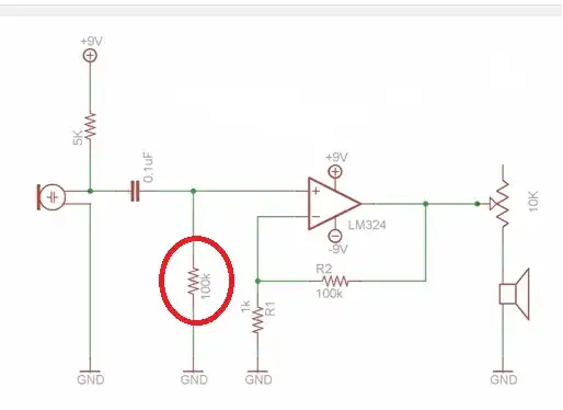
I'm using a different opamp, the NE5532, which probably has higher bias currents, but which is commonly used in audio. The circuit otherwise is basically the same, except that I've wisely added an output cap as well... which is not a bad idea as you shall below why:
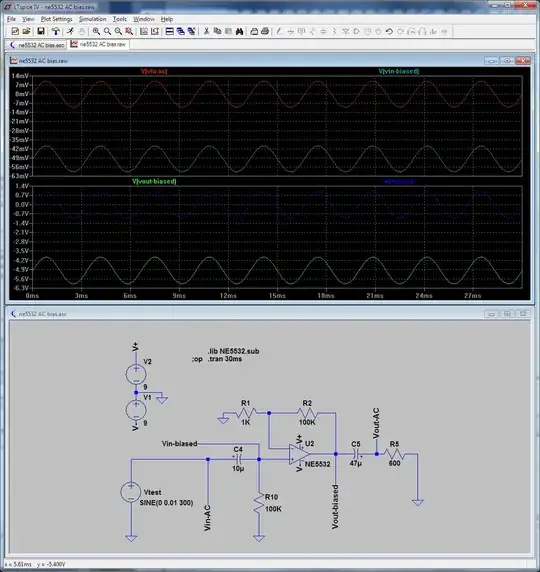
There's about -5V of DC bias on output (before the cap). And these originate from the amplfication of the input bias voltage (about -50mV) caused at the input by the current flowing through the positive-input biasing resistor R10. Now watch what happens when we increase this R10 resistor to 100Mohm (or remove it altogether).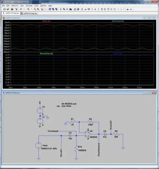
The output goes into saturation; we have a hint why it happened because of the input offset voltage is also much higher than before (about -200mV instead of -50mV).
You can also do a parametric sweep of some values for R10, in this case 50K, 100K, 150, 200K, which turns out to be enough to cause output saturation with the NE5532.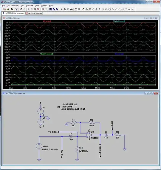
And if you're curious about eliminating (as much as possible, in practice it won't be perfect) the offset voltage, then you need to add another resistor (R3=R10) to roughly match the input currents. This is only relevant if you want to live without the output cap as the circuit from the question tries to do. But that's basically another topic, which is the subject of a different question here.)
Finally, I've uploaded the source code for one of the above (very similar) circuits, namely the 3rd/parametric one, so you (newbies) can experiment yourselves. You need the NE5532 opamp macromodel for the code to work as is (although practically any opamp will work the same way but will cause saturation at different R10 values) and of course the LTSpice IV simulator.