4

I repair electric powered steering systems for cars, especially Fiat, Alfa, and Lancya (Delphi manufacturers), and I'm in need of making some tool to test these reparations. I mean just turning it on, for example.

I have researched during some time, and I figured I need CAN bus signals to be simulated as the eps ECU is receiving ignition packets from CAN. Here I go...

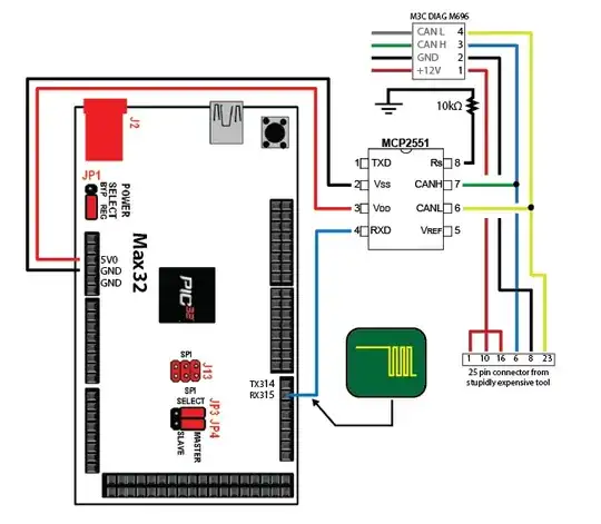
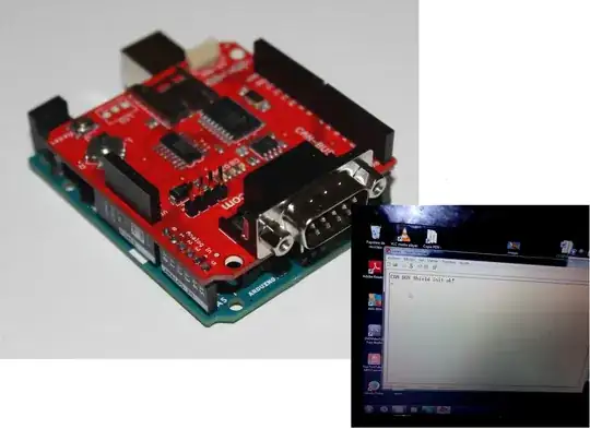
I need to know what way I could read and send CAN packets from/to the bus. I mean, what tool or anything else. I have been trying with Arduino Uno + a SparkFun CAN BUS Shield, but I don't get any results. When everything is connected, my serial console isn't sniffing any packets. I have connected all correctly, I think, and tried different bit rates, changed Arduino boards and shield, tried many different examples. I invested lots of hours with no profit... I was using SEAT Ibiza 2010 for I+D, connected CAN-H and CAN-L on the OBD port, in the CAN lines from the radio, etc...

Any idea of what could be wrong is welcome, as is a new method to make my project...

Information:

ARDUINO AND SPARKFUN SHIELD AND SERIAL CONSOLE

Libraries Used

UPDATE 2 (28/12/2014): I used a multimeter because I dont have a oscilloscope. Reading the voltages are always giving me plain 2.5V on CAN-H and CAN-L, I get this readings at Arduino CAN-H CAN-L and in OBD2 Port (Pins 6 and 14)

UPDATE 3 (29/12/2014): I'm planning to switch to some programming language with a CAN interface, any suggestions are welcome, thanks!

UPDATE 3.1 (30/12/2014): Definitely, I'm taking another way to do this, I'm waiting Kvaser and ECOM to reply me in their support emails. That way we may know if their tools fit with my project. I will keep you updated, thanks for all the help guys! :)

  • My best guess is that your CAN receiver is receiving the broadcast packets. But since your identifier doesn't match with the destination address, your CAN receiver simply drops the packet. You might be looking for something like this http://www.ebay.com/itm/ELM327-V1-5-OBDII-OBD2-CAN-BUS-USB-Auto-Car-Diagnostic-Interface-Scanner-Tool-/321624835220 – Damon Dec 26 '14 at 05:49
  • @Nick Alexeev but as i think the code used is for sniffing all data roaming in this lines, shouldnt it show something? X_X Anyways, i had ordered the ELM already, but i dont know if i can send custom HEX packets to CAN Bus for my purpose of simulating signals.. Thanks for your attention! :) – Aaron Aguayo Martinez Dec 26 '14 at 12:57
  • What is "I+D"?​ – Peter Mortensen Dec 26 '14 at 19:23
  • With an oscilloscope you can determine the bitrate and if the CAN bus signals are actually present at the CAN bus shield. – Peter Mortensen Dec 27 '14 at 00:34
  • Can you post the code you are using? – Peter Mortensen Dec 27 '14 at 00:41
  • Can you provide a link to the SparkFun CAN bus shield (by updating your question)? – Peter Mortensen Dec 27 '14 at 00:46
  • Question *[Reading from CAN bus of a Chevrolet Cruze using an Arduino Uno](http://electronics.stackexchange.com/questions/95070)* is very similar to yours (Arduino Uno with a CAN bus shield from SparkFun). You may want to explore the information therein, experiment, and return here (update your question with the found new information). You are welcome to ping me via Email or Twitter when you are done, so we can get a proper answer to your question (instead of just suggesting to buy expensive new equipment - I don't see any reason why this should not be working, at least not partially). – Peter Mortensen Dec 27 '14 at 00:47
  • @Peter Mortensen I+D is "Investigation and developing", i will update the post with the url of what i used, the code are in the rar i uploaded to dropbox, i tried all of them, but no sucess. About that question of chevrolet cruze, i did read it, but nothing of that solves my problems... i cant waste that much on new equipment, and my main interest after my work is to learn about can bus, with arduino and sparkfun i should get to read atleast the messages.. any tip? if you need any info just tell me and i can provide anything, a video or anything else. – Aaron Aguayo Martinez Dec 27 '14 at 20:51
  • Tip: use an oscilloscope to read off the bitrate and some COBIDs (I don't think COBIDs are affected by [bit stuffing](http://en.wikipedia.org/wiki/CAN_bus#Bit_stuffing)). Both CAN-H and CAN-L should have signals with respect to ground. Do the measurement as close as possible to the CAN transceiver on the Arduino. If you don't have access to an oscilloscope, use a voltmeter to follow the signals from the car's CAN bus to the Arduino shield - both CAN-H and CAN-L will have a characterisic (average) voltage. Post the results by updating the question. – Peter Mortensen Dec 28 '14 at 19:27
  • If you find a COBID then this can be used in the software - depending on the software, it may require you to use a particular COBID. Even if you want to look at all COBIDs this is an important step to establish wether any message can be received. – Peter Mortensen Dec 28 '14 at 19:31
  • The 2.5V on both CAN-H and CAN-L may indicate that there isn't any traffic (or very little traffic). – Peter Mortensen Dec 28 '14 at 23:16
  • What is the (exact) voltage if you measure between CAN-H and CAN-L? (Post the result by updating the question.) – Peter Mortensen Dec 28 '14 at 23:22
  • @Peter Mortensen and how could it be? isnt car supossed to be sending packets in this lines? in the examples I followed, people were getting lots of messages with CAN ID and HEX bytes.. Btw, what you mean with COBID? – Aaron Aguayo Martinez Dec 29 '14 at 00:35
  • We don't know yet - we are in troubleshooting mode right now. We ***expect*** there to be traffic on the bus and thus the (average) voltage difference between CAN-H and CAN-L should be somewhat different from 0 volt. How much depends on the traffic. We are also near blind without an oscilloscope. (COBID is the first part of a CAN bus message. It is often 11 bit or 29 bits ([J1939](http://en.wikipedia.org/wiki/SAE_J1939)) long.) – Peter Mortensen Dec 29 '14 at 00:44
  • I could ask a friend that may have a oscilloscope, what I need to check with that? @Peter Mortensen – Aaron Aguayo Martinez Dec 29 '14 at 01:11
  • First, determine the bit time. This is just the smallest time between transistions (low to high/high to low) - the transition times are a multiplum of the bit time. E.g. if the bit time is 1.5 µs, the time between transistions will be either 1.5 µs, 3.0 µs, 4.5 µs, 6.0 µs, 7.5 µs, etc. Measure between CAN-L and CAN-H (requires floating ground) and trigger on the same channel (e.g. CH1) with a trigger level of 0.5 V, trigger in DC mode (AC mode will also do [if the oscilloscope is not flawed](https://www.youtube.com/watch?v=kcOdzFaIYNE)). Try to determine the bit time as accurately as possible. – Peter Mortensen Dec 29 '14 at 01:53
  • Second, read out the bits for an entire message and try to make sense of it (the [bit stuffing](https://en.wikipedia.org/wiki/CAN_bus#Bit_stuffing) complicates it) - for instance, are 11 bit or 29 bits COBIDs used. It is probably easiest to do for the shortest messages. – Peter Mortensen Dec 29 '14 at 02:06
  • I couldnt get and oscilloscope from my friend, any other tips @PeterMortensen ? Thanks for your help – Aaron Aguayo Martinez Dec 29 '14 at 21:29
  • I'm getting 3.7V and 1.3V in CAN-High and CAN-Low in the CAN lines to the radio, could OBD2 Port be protected? If so how can I bypass it? – Aaron Aguayo Martinez Dec 29 '14 at 21:32
  • (Still not receiving any info anyway with the radio can lines) – Aaron Aguayo Martinez Dec 29 '14 at 21:32
  • I think you should persue the signals on the CAN bus to the radio first. You need to find the bitrate. You could use a standard [Schmitt trigger](http://en.wikipedia.org/wiki/Schmitt_trigger) with voltage thresholds of 2.5 V and 2.9 V. Feed the output of the Schmitt trigger into a digital input on the Arduino. Write a program to find the bit timing. For instance, set up a timer/counter with sufficiently high time resolution and busy-wait for transistions. When there is a transition, output the timer/counter value to standard output so it appears in the terminal in the Arduino IDE. – Peter Mortensen Dec 31 '14 at 02:41
  • - con't. There should be a characteristic minimum time difference, corresponding to the bit time (repeated many times). (In the output, make the program only output values for the first, say, 20 transitions). – Peter Mortensen Dec 31 '14 at 02:42

3 Answers3

2

The Arduino CAN shield is pretty cool if you want to build an embedded computer to play with CAN. However, if I understand correctly, you are building a one-off tool for your personal use (or will merely use an off-the-shelf tool if one exists for the right price). For that reason, I urge you to consider writing PC software rather than embedded software to interface with existing, low-cost CAN hardware interfaces.

Charlie Miller and Chris Valasek used this so called ECOM tool and wrote software which interfaces with it. The ECOM tool appears to have an API and example driver. Their car hacking white paper and software will give a pretty good starting point for interfacing a PC to a car. Softing also makes PC CAN interface hardware, but I am having trouble accessing their website right now, so I won't link it.

There are also several full-fledged, commercial software tools for analyzing and simulating CAN on a PC as well. Vector's CANoe is a well known (and expensive) tool for that purpose.

downbeat
  • 395
  • 1
  • 6
  • Hello @downbeat, first of all sorry for not answering, I didnt see your answer. What specific interface (if it's cheap, better :P, if not, I need it anyways ) can I use for interface with the car with my IDE? What language to use? I know java, a bit of C++, any info or examples for it would be very appreciate. – Aaron Aguayo Martinez Dec 29 '14 at 21:34
  • I do not have the reputation to comment on the EE stack exchange. Most likely there is some sort of driver supplied with any sort of low-cost tool. The ECOM tool I mentioned is $180. That ELM327 is $7-$21. Either one will require some amount of programming. It looks like that ELM device uses an AT command set over RS232. I would interface with that using Python, but it should be pretty well dead simple once you get the hang of the device. – downbeat Jul 25 '15 at 13:49
  • I recently found the USB2CAN (http://www.8devices.com/usb2can) tool, which is even cheaper, selling at $65 as of this writing [http://shop.8devices.com/index.php?route=product/product&product_id=54]. I have used it on Linux, but not Windows. I don't know how rich the included software is, but you can certainly write your own scripts to interface with the driver directly. On Linux, there are some pre-existing CAN tools such as cansend, candump, cangen and canplayer. – downbeat Jul 25 '15 at 13:51
1

If you're open to buying something off the shelf for a few hundred dollars, Kvaser's Leaf products are pretty easy to use. They let you send pre-recorded sequences of packets and monitor the bus. You can get one with an OBD-2 connector if that's what you need.

Building your own test equipment is fine for a personal project, but if you're making money off of these repairs, it's probably better to start with something you know is reliable.

Adam Haun
  • 21,331
  • 4
  • 50
  • 91
  • thanks for the tips Adam! could you leave me a link? I would prefer making my own as it shouldnt be very hard, so later I can improve my tool for my new needs, regards! – Aaron Aguayo Martinez Dec 28 '14 at 03:32
  • 1
    Here's a link to the low-end model: http://www.kvaser.com/products/kvaser-leaf-light-v2/ – Adam Haun Dec 28 '14 at 04:10
0

Having managed to eventually get numbers from a CAN bus with an embedded controller, I believe the biggest problem you're experiencing are the vendors' examples not properly initializing the controller's registers for CAN quanta and sample timing.

Curbing the popular CAN shields' efforts is the 16 MHz crystal SparkFun and Seeeed use. Then the low-speed Arduino isn't well suited for moving serial data. None of the sample code on the Internet works because they are all canned examples for 1 Mbit/s...

Some microcontrollers have CAN controllers built-in (sadly, almost none have transceivers). I used a ChipKIT Max32 and a MCP2551 IC via breadboard in the circuit below. Additionally, I tapped into the transceivers on the SparkFun and Seeed's CAN shields to get Tx/Rx data. The ChipKIT's Max32 has two CAN controllers and an 80 MHz CPU clock, so it is well suited for CAN experimentation. Using an online calculator, I was able to set up the PIC32's controller on the first try.

I suspended my development on CAN work for other projects, but an affiliate has coaxed an Arduino Uno with CAN shields into reading from a 500 kbit/s bus. I looked at the code he recently shared with me, but I couldn't find how the MCP2515 controller's timing was set or how it differed from the example code.

The next development board I'm trying is Ti's Connected LaunchPad TM4C123GXL. It has CAN controllers, USB OTG, lots of I/O and is US$13.

Enter image description here

Peter Mortensen
  • 1,676
  • 3
  • 17
  • 23
Krista K
  • 503
  • 6
  • 17