2

I have an FT232RL connected to an AVR Atmega2184P (running the Arduino core) UART. The microcontroller has two power supplies - a LiPo battery (VBat), and USB power (Vin). The way I've designed the circuit is that if the USB is plugged in the battery is disconnected from the circuit and Vin powers the entire circuit. When the USB is unplugged, VBat takes over

The VCC and VCCIO on the FT232 is connected to Vin. Therefore the FTDI chip should only be powered on when the USB device is connected.

I'm noticing weird behavior when the battery is plugged in but the USB is not. As soon as I initiate the UART bus on the microcontroller, and current is sent down the RX and TX lines, the FT232 powers itself up. What is strange is the power is then transferred into the Vin power rail.

This is affecting other parts in my circuit that rely on there not being any power in Vin when the USB is unplugged. If my code doesn't initiate the UART bus, everything works as it should.

Has anybody seen this behavior? I can't see any reason why the FTDI chip would be relaying power back into the VCC line.

I've tested this with multiple processors (different Arduino boards), and multiple FTDI breakout boards. Initially thought it might be a chip issue, but the behavior described is consistent across each device.
darudude
  • 335
  • 2
  • 9
  • 1
    See http://electronics.stackexchange.com/questions/109092/preventing-parasitic-powering-of-ft232rl-by-atmega328p and http://electronics.stackexchange.com/questions/141547/a-circuit-to-prevent-parasitic-powering-of-ft232rl-by-mcu-will-it-work – Passerby Dec 23 '14 at 05:03
  • Thx for the links guys! That definitely seems to be the issue. – darudude Dec 23 '14 at 05:35
  • @Passerby - I saw in the other questions you recommended optocouplers. Another option I was thinking was that instead of using the FT232 in Bus Powered mode (i.e. USB powers FT232), to operate it in self-powered mode instead. I was planning on powering the FT232 from my VCC5 line (5V regulated supply that both Vin and Vbat feed into). That way, my micrcontroller and FT232 are always powered from the same bus, and I won't run into this issue, as Vin is isolated. Does this make sense? – darudude Dec 23 '14 at 05:38

2 Answers2

3

Your FTDI chip is being powered through the input protection diode on the input line.

Although FTDI does not appear to have shown it in their data sheet the inputs of IC chips are very often protected from ESD by having a diode clamping structure that clamps input pin voltages to be between GND and VDD. When the supply pin is not connected to anything a high level signal on the input pin can source current through the upper clamp diode and "power up the chip".

Michael Karas
  • 56,889
  • 3
  • 70
  • 138
2

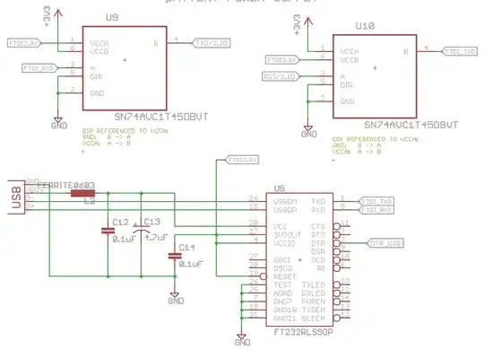
I can confirm that using two 74LVC1T45 will work, as answered in (my question): A circuit to prevent parasitic powering of FT232RL by MCU, will it work?

This is my working circuit:

enter image description here

I use a jumper (not shown) to connect FTDI3.3V as the 3.3V supply to the rest of the circuit.

geometrikal
  • 4,921
  • 2
  • 23
  • 41
  • DO you only connect the jumper when the FTDI is in operation? Or is the jumper permanent? I'm looking for a solution where no manual intervention is necessary. – darudude Dec 23 '14 at 12:31
  • @darudude The circuit is normally powered by the battery using a LTC3525-3.3v boost converter, except for the FTDI which is bus powered. The jumper lets the FTDI power the rest of the circuit when no battery is present; it is not permanent. To automatically switch between the two you need some extra circuitry. Your circuit runs on 5v? There are quite a few ways to do this... – geometrikal Dec 24 '14 at 21:32