I built a low dropout regulator following experiences building a discrete linear regulator. The circuit is simple like this:
simulate this circuit – Schematic created using CircuitLab
I would like to know how to test the maximum voltage inout and output, current carrying and heat dissipation ratings of this circuit with parts as specified in circuit, as well as its minimum voltage dropout.
By supplying a regulated 5.5V into this circuit I can get the maximum of 5.4V at the output under 30mA load. Does this spell a minimum 0.1V dropout at 30mA?
I also got a minimum of 2.5V voltage output without load. How to modify this regulator so that it can shut the load down by turning the pot one way all to the end?
Also is the op-amp getting power from the unregulated input a problem?
--- EDIT ---
Since this circuit is not protected, how to add overcurrent protectection? I am considering using LM358 instead of LM741 as the op-amp chip, and how to construct the current sensing and overcurrent protection circuit using the extra op-amp from LM358, a shunt resistor and a few more MOSFETs? (I have 2N7000, BS250, IRF4905 and IRF540 spare parts lying around in bulk)
--- EDIT 2 ---
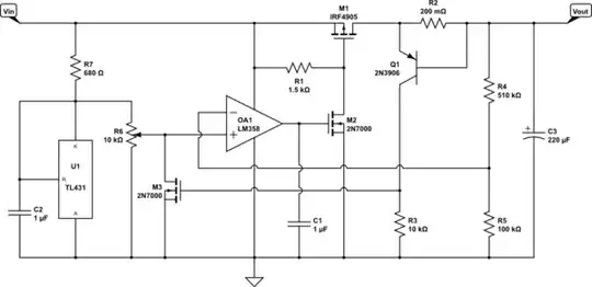
Rounding up suggestions, does this seem like a better circuit?
The reference is modified per @SpehroPefhany's suggestion to use a TL431 powered through a 680Ω resistor. The old 741 is swapped out with OPA2134 dual rail-to-rail op-amp (expensive!) per @andyaka's suggestion. Some frequency compensation is attempted using capacitor C3 at the gate of pass transistor M1.
My intention of the overcurrent protection is like this:
The second op amp in the OPA2134 package is wired into a differential amplifier, monitoring the voltage difference between current shunt resistor R4. When the current approaches 4A the voltage drop across R4 increases to the point that the voltage output of the differential amplifier OA1b approaches the threshold voltage of 2N7000 and start to push it on, pulling the voltage at the inverting input of error amplifier OA1a lower, pushing the gate voltage of M1 higher and start to shut M1 down.
--- EDIT 3 ---
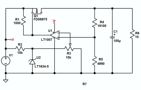
Rounding up suggestions again, would this be better?
The op amp is no longer driving the pass MOSFET directly, and current shunt voltage is directly matched against the threshold voltage of a MOSFET PNP BJT. This should be able to eliminate the need for a RRIO op amp. I am still using a relatively modern LM358 but is 741 suitable here now?