8

Is there a circuit which can transform a tri-state (low, high-Z, high) output to three voltage levels?

Ideally, the circuit will use only passives and diodes.


Would a simple voltage divider across the pin do the job?

             Vdd
              |
              R
              |
tri-state-----+-------out
              |
              R
              |
             Vss
fadedbee
  • 994
  • 9
  • 24
  • 1
    wow, that sounds pretty trippy. Is there some other part of the system that we can work with to get you the same results? Can you expand on the rest of what you are working with, maybe with a schematic? There may be a simpler way. – KyranF Dec 19 '14 at 09:36
  • I'm playing with an 8 pin MCU and was idly wondering if the three possible states of the output pins could all be used. I'm already aware of Charlieplexing. – fadedbee Dec 19 '14 at 09:39
  • What do you intend on doing with them once you have them? – Ignacio Vazquez-Abrams Dec 19 '14 at 09:41
  • Two distinct brightnesses of an LED (plus off), using just one pin. – fadedbee Dec 19 '14 at 09:42
  • 3
    If you are driving a load, you may want to use an op-amp buffer after the "out" signal. – KyranF Dec 19 '14 at 09:49
  • Would a transistor do the job? Why an op-amp specifically? – fadedbee Dec 19 '14 at 09:50
  • 2
    A transistor doesn't use the voltage levels properly, how do you expect that to work? An op-amp set as a simple "voltage buffer" will mean that you can connect an LED to the output of the op-amp and it will reflect the voltage level on the input, as the output, but also be able to drive current properly. voltage dividers cannot drive current properly, through an LED, and retain their levels. – KyranF Dec 19 '14 at 09:56
  • 1
    If you want to dim an LED, you can do that without any fancy circuitry - use PWM to do it! – Nick Johnson Dec 19 '14 at 10:10
  • Excellent idea, thanks, but I'm still interested in the general concept too. – fadedbee Dec 19 '14 at 10:59
  • 1
    @NickJohnson: PWM without an analog reconstruction filter doesn't dim an LED... it causes a reduction in **average** light output, which appears dimmed to the human eye, but that's due to persistence of vision. Other light sensors typically don't have persistence of vision. – Ben Voigt Dec 19 '14 at 21:25

4 Answers4

7

A simple potential divider will work, and is commonly used for this.

Vhigh, Vlow, Vdd/2 levels for 1,0,Z respectively.

Remember the 0/1 to Z transition will be relatively slow because it is not actively driven (just the RC time constant); or in other words, the Z state has a low drive capability (5k\$\Omega\$ source resistance).

schematic

simulate this circuit – Schematic created using CircuitLab

akellyirl
  • 4,117
  • 1
  • 16
  • 30
  • 5
    Note that the drive power of the Z state will be much lower, too, since it has the equivalent of 5k series resistance rather than the much lower resistance of the gate driver. – Nick Johnson Dec 19 '14 at 10:10
  • Adding a third resistor in series with the 3-state output will allow further control over the output behavior; adding a fourth resistor directly from the output to either VDD or VSS will make it possible to establish any three desired voltage levels. – supercat Dec 19 '14 at 19:01
6

Yes, you can connect a voltage divider to the output pin, say, using equal resistors. That'll give you half the supply voltage when the output is HIGH-Z, and the normal HIGH and LOW when the output is in those states. Two resistors, no diodes needed.

John Honniball
  • 2,799
  • 11
  • 10
2

I use the same arrangement in the laboratory of digital electronics to demonstrate to my students the idea of the tri-state output (of the unidirectional buffer 74LS244). To directly visualize the output state, we connect two LEDs in series to each resistor. Thus, when the output is OFF (HI), both the LEDs light. At low or high output voltage, one of them is shunted by the internal transistor, and extinguishes. We also connect a LED network (two LEDs - red and green, in parallel) between the outputs of the chip and voltage divider. Also, we replace the voltage divider by a potentiometer and move its slider; in HI state, it produces a voltage varying between the rails.

You can replace the voltage divider by a resistor connected between the output and some voltage between the rails (usually, 1/2Vcc). In the laboratory, we connect it to the output of a pulse generator (when the output is in HI state, we see the pulsess; otherwise we see high or low voltage depending on the input signal).

Circuit fantasist
  • 13,593
  • 1
  • 17
  • 48
1

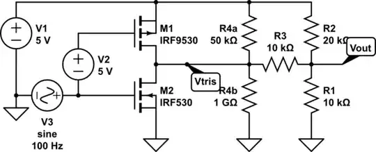
It's possible to have low/float/high output any three voltages between the rails by using the four resistor circuit shown below (note that only one of the R4 resistors will be needed; which one will depend upon the desired output voltage when the output is floating). The circuit below will output 1/2/3 volts when the output is low/float/high.

schematic

simulate this circuit – Schematic created using CircuitLab

Assuming VS is the supply/output high voltage, and the desired top/middle/bottom voltages are VT, VM, and VB respectively, assign values to R1 and R2 such that R1/R2=VB/(VS-VT) [in this example, 10k/20k = 1V/(5V-3V)]. Resistors may be scaled up and down together as convenient. Next, assign R3 so that VB/R1+VB/R3 = (VS-VB)/R2 [in this example, 1V/10K + 1V/10K = (5V-1V)/20K.] That will make the output yield the correct voltages for 'high' and 'low' cases, but not necessarily for the 'float' case.

If the 'float' voltages is too low, add R4a to raise it; if it's too high, add R4b to lower it. In this example, it's necessary to raise the voltage. When the output is at the correct voltage, 0.2mA will flow through R1 and 0.15mA through R2. That means 0.05mA must flow through the series string of R4a+R3 which has 3 volts across it, so the total resistance of that string must be 60K; R4a must thus be 50K.

supercat
  • 45,939
  • 2
  • 84
  • 143
  • An interesting idea... like a bridge circuit where we short the upper or lower legs of the left half-bridge (R4a-R4b) and observe the output of the right half-bridge (R2-R1)... Actually, the voltage divider R4a-R4b acts only when the output is in HI state; otherwise, it is overrided by the closed transistor. But still there is something strange in this connection of a high-resistive circuit after a powerful CMOS stage... – Circuit fantasist Dec 20 '14 at 11:58
  • 1
    The R4a/R4b isn't intended as a "voltage divider"; the idea is that only one or the other would be populated; the 1G resistor is intended to represent an open-circuit. – supercat Dec 21 '14 at 22:54