0

I was looking for a way to simulate a button pressing with an arduino in a black-box circuit I cannot modify (I have no GND), you can see it in my previous question and question.

Then, reading this post, I found the MAX4544:

enter image description here

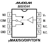
It is not very clear to me how this IC differ from a relay that operates on two DC circuit. It has a control pin that can move a digital switch that open or close a circuit. Relay are defined from wikipedia as "A relay is an electrically operated switch". Can anyone explain me in plain english please?

nkint
  • 963
  • 5
  • 14
  • 27
  • Are you asking what a relay is? Or what the difference is between a regular relay and this component? – Nick Johnson Dec 18 '14 at 11:39
  • I've used a Photovoltaic relay in a similar situation to yours (opto-isolated MOSFET switch). I answered your other question with the details (http://electronics.stackexchange.com/questions/144376/solid-state-relay-or-equivalent-alternative-to-drive-6v-dc-from-a-3-3v-micro/144442#144442) – akellyirl Dec 18 '14 at 11:59
  • @NickJohnson here I'm asking difference between a regular relay and this component – nkint Dec 18 '14 at 12:33
  • @NickJohnson, thanks for the answer, I'll comment it – nkint Dec 18 '14 at 12:33

2 Answers2

1

Relays give you some degree of isolation between the control signal and the switched circuit, so you don't have to care about things like ground potential differences or high-voltages on the switching side possibly appearing at the control input.

The MAX4544 does not provide that isolation. As an alternative, the IR PVT312 does provide the isolation you require because it's an opto-isolated MOSFET switch and is described by IR as a "HEXFET Power MOSFET Photovoltaic Relay".

akellyirl
  • 4,117
  • 1
  • 16
  • 30
  • This IC is not suitable in the situation described, because it can only switch voltages between its supply rails. If he really has no external ground reference, the two circuits have no shared ground, and so there's no way to ensure that. – Nick Johnson Dec 18 '14 at 11:45
  • @NickJohnson Thanks for pointing that out. I edited the answer to address your comment. So it is no longer a valid issue. – akellyirl Dec 18 '14 at 12:09
1

This IC is a type of digitally controlled analog switch. They work internally using FET transistors, and they act generally like a (fairly high resistance) switch, but only for voltages between the IC's ground and power rails. Since you have no control over the relative ground levels of your two circuits, an IC like this won't work in your situation.

To address the implied question of "how do I switch this unknown circuit", an optocoupler will certainly work, but a simpler solution, if both devices do not need to be powered from AC, is to simply designate the more negative of the two switch terminals available to you as GND, connect that to your Arduino's GND pin, and switch the other pin to GND with a simple FET transistor. This only works if the two devices truly have no shared ground reference, such as both being connected to AC power, or running off the same batteries.

Nick Johnson
  • 7,739
  • 3
  • 28
  • 44
  • Ok so MAX4544 need a common ground, very clear. I don't have it. Both circuits are powered from the same AC power. I though from this (answer)[http://arduino.stackexchange.com/a/6544/1335] that optocoupler not works in this case (and anyway I didn't manage to let it work, see the related question). Can you post an example of how to use a FET transistor please? It is not very clear sorry – nkint Dec 18 '14 at 12:39
  • The optocoupler will probably still work. The thing to do first is to figure out what you have to work with. Maybe one of the terminals of the switch is already at gnd? What's the voltage of each terminal relative to your Arduino's gnd when the switch is open? How much current flows when you close the switch with a multimeter set to measure current? – Nick Johnson Dec 18 '14 at 13:31
  • Ok I'll measure as soon as possible, anyway is it connected right in the )question I have asked with the schematics)[http://arduino.stackexchange.com/questions/6542/arduino-due-and-optocoupler-4n25]? – nkint Dec 18 '14 at 16:44
  • @nkint I don't know - a schematic would be much more useful. Bear in mind that you can't just take voltage readings on the isolated side compared to Arduino's GND - that's the whole point of having isolation, the GND levels needn't be the same! – Nick Johnson Dec 18 '14 at 16:47