My EDA software (PCAD, but I guess others do this too) adds thermal reliefs on vias in a copper pour. What's the use? Vias aren't soldered. (I know why you use them on regular PTH pads)
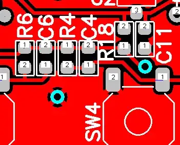
-
It looks like a bad configuration default at best, or lazy coding at worst. That is, treating vias and through-holes as the same object to slightly simplify the program: "hey, since we implemented through holes, look: now just five more lines of code in two places give us vias!!!". – Kaz Apr 03 '14 at 06:22
4 Answers
What the other guys have said is very true. I'll add that about 10 or 15 years ago I stopped using thermal reliefs. Since that time, maybe 30-50K PCB's have been manufactured and I've never had a problem.
In a production environment soldering to pins/pads/vias/holes directly connected to large planes isn't really an issue due to the temperature profile of the ovens, and that the ovens tend to heat the whole board and not just the pads that are being soldered.
When hand soldering on a PCB without thermal reliefs there can be an issue, as the others have pointed out, but in my opinion the advantages of no thermal reliefs are far greater than easier hand soldering.
Here's some of the advantages of no thermal reliefs:
- Greater heat transfer to the planes on the PCB. You see this the most on QFN's and other packages that have a ground pad on the bottom of the part in the center. This pad is intended to transfer heat to vias and then to the ground plane.
- Easier routing and fan-out of BGAs and other dense parts. Particularly when putting planes under the BGA.
- Less chance for the via to get messed up due to plating, or drill accuracy issues, or other PCB manufacturing problems (not a huge benefit, but a benefit none the less).
So, in the end, I don't use thermal reliefs and I've had zero problems (other than the occasional hand-solder issue which is easy to overcome).
-
1
-
-
Where I work we still use thermal relief for through hole pads. We don't use it for vias. We sell thousands of products a month and we don't have any trouble. – Daniel Grillo May 19 '11 at 14:27
-
5"Right. I don't use thermal reliefs anywhere" -- Heh, try desoldering a large through-hole component (TO-220 or a 1N540x 3A diode) on a 6oz copper board when you do that. – Jason S Jul 18 '11 at 19:14
-
2Desoldering a part is an admission that your design isn't robust enough to work forever (in the opinion of management, at least) ;) – Adam Lawrence May 17 '13 at 13:19
-
3How many layers in your boards? Simple 2-layer boards are not as bad as 6 or 8 layer boards with ground planes sucking heat away in every direction. – Spehro Pefhany Apr 03 '14 at 02:01
-
5I tried this and with thru-hole components on boards with power planes; the wave solder does not get pulled up through the via on power pins with no thermal relief. The board still function electrically but the power pin solder connections are definitely not ideal. – bt2 Feb 01 '15 at 13:18
IPC2221 Section 9.1.3 says:
9.1.3 Thermal Relief in Conductor Planes Thermal relief is only required for holes that are subject to soldering in large conductor areas (ground planes, voltage planes, thermal planes, etc.). Relief is required to reduce soldering dwell time by providing thermal resistance during the soldering process
I think most of times is not necessary to thermally relive a via.

- 7,659
- 18
- 51
- 69
To ensure that the copper pour doesn't conduct the heat away when the board is soldered, which will result in bad solder joints. Vias are sometimes filled with solder, to increase reliability.
Thermal reliefs are optional with the software I use; you can probably make them ordinary vias, if you wish. Tent them, if you don't want them soldered.

- 38,774
- 2
- 60
- 96
-
Agreed! When the hole is in a huge ground plane, it becomes almost impossible to solder properly with a regular iron! – Toybuilder May 19 '11 at 11:12
-
2@Toybuilder - true, but my point is about vias, which aren't soldered at all! – stevenvh May 19 '11 at 11:35
-
-
@Leon - I've hardly ever seen vias filled with solder. How would you fill a 0.1mm via, like between the pads of a 0.5mm pitch BGA? And even bigger vias (the one in the image is 0.5mm) are almost always covered with solder resist. – stevenvh May 19 '11 at 11:39
-
-
3@Daniel Grillo "Tent" is the "proper" word. I agree that it's a dumb term, but people know what it means. Where if you say "flooding" then they might not understand. Normally "flooding" refers to copper planes on a PCB that are not on the normal power or ground layers. – May 19 '11 at 13:03
-
@David, Ok. Thanks for your explanation. I suggest "flooding" because I thought it was more commonly used. – Daniel Grillo May 19 '11 at 13:10
-
4@stevenh: It's very common with prototypes to solder wires to vias, for test points if nothing else. If a board (proto or early production) needs to be altered, having a via available to solder to can make rework much easier. – supercat May 19 '11 at 15:13
-
1Sometimes, the other end of the via goes right to a SMD pad, and heat will get sunk to the planes through the via. – Toybuilder May 19 '11 at 18:12
A proper thermal relief on TH connections is a must for Lead free wave soldering. It is impossible to get 50% solder fill (or 47mil, which ever is less) on ground connections without thermal relief, especially on +90mil thick PCBs. There is IPC 2221A section 9.1.3, which has very good recommendation. I have seen best results on two 10mil web spoke designs for +3 ground plane PCBs.