2

I want to design a voltage divider for my Arduino Analog input pin, to be able to sense the change in voltage in a 9V, 250mA circuit (without loading it).

Ive programmed the Arduino so that as soon as a drop in voltage is sensed, my Arduino will perform rest of its job (programmed to create a specific series of delays that I need).

In other words how can I create a signal that is proportional to the changes in the 9V signal that operates at 250mA without drawing any extra current from it nor by creating any voltage drops in the original circuit.

The link below gave great information on how I can use opto-couplers and that would have solved my problem but CNY17 cannot operate over 60mA (otherwise I would have just put that in series with the original circuit?) How can I use a 12 V input on a digital Arduino pin?

Any help is much appreciated!

edit1: Let me try to describe the problem better. I had a feeling it came across as vague in my attempt to minimize the description. The 9V circuit that I was referring to is basically a water flow meter that starts spinning when a flow is sensed and this chops the 9VDC applied across it into pulses, an irrigation controller connected to the other end(this is what applies the 9V across the flow meter) measures the frequency of these pulses and determines the flow of the water(in gpm) Using Arduino, I am building a circuit that will initiate a series of delays as soon as it senses a flow. 9VDC=no flow, chopped 9V=flow However since I cannot connect 9V directly to Arduino, I need some sort of a voltage divider, but the reason it needs to be isolated from this 9V flow meter circuit is because the irrigation controller is calibrated to read any changes in the voltage and I don't want it to give false reading. I guess I can use some current from the original circuit -it currently runs at 230mA and I dont know how much I can add on to this without confusing the controller - something that must be tested to find out. Also I would imagine that a small voltage drop (1-2volts) should be okay?

for example: I was considering using an optocoupler- with the photodiode in series with the flowmeter cicuit, but I dont want to reduce the original current (230mA) by any significant amount lest it give a false input to the irrigation controller. At the same time, the optocouplers I am looking at do not allow anything more than 60mA.

Hope this helps understand the problem a bit better. I am happy to answer any more questions.
Ameya
  • 23
  • 1
  • 4
  • 1
    Strictly speaking, if you want to make a measurement, you will need to draw some current for that. This current can miniscule, but it will be nonzero. The following questions will help us better understand your problem. Why is this additional loading a problem for you? What's the maximum loading current you can have? Give a number with some justification. Please don't say "as small as possible". Finally, what's the purpose of this voltage measurement; what are you trying to achieve? – Nick Alexeev Dec 16 '14 at 05:22
  • 1
    In addition to Nick Alexeev's questions, what is the amplitude of the voltage drop you're concerned about on the 9 volt line? – EM Fields Dec 16 '14 at 08:20
  • Feels like you should be considering a comparator – Scott Seidman Dec 16 '14 at 12:11
  • @NickAlexeev Let me try to describe the problem in detail: – Ameya Dec 16 '14 at 18:40
  • @NickAlexeev Please see the original post- its updated with a detailed description. Thankyou for your help – Ameya Dec 16 '14 at 19:11

4 Answers4

1

The easiest, and cheapest, method would be use a voltage divider with large value resistors (both greater than 100k in this case). If you connected your 9V circuit output in series with a 200k resistor and 100k resistor, the voltage in the middle of the resistors would be 3V, comfortably in the middle of the Arduino's 5V operating range.

For practical purposes, a large value voltage divider will not load your source circuit down as, from Ohms Law, 9V divided by the total resistance, 300k, is 30uA. This is 0.01% of your source current, and can thus be ignored.

If this small current cannot be ignored, look into op-amp circuits, which will have input currents in the nA or less range.

EDIT: Yes, loading of the ADC circuit could be a problem. The easiest way to prevent this would be to connect the large value voltage divider, which I describe here, to the op-amp voltage follower shown below. This would both drop the voltage to a level the arduino can handle, and prevent any ADC circuit loading.

dataBus
  • 66
  • 3
  • 1
    There is another potential problem. Sometimes ADC inputs can be in the 100's of k range in terms of input impedance. They sometimes have their own voltage dividers inside. When this happens, high value resistor dividers can't be used. The OP should check to see if the ADC input current or input resistance is specified. – user57037 Dec 16 '14 at 04:56
1

The best thing for you is to use the op-amp buffer. You can read about it here:

http://en.wikipedia.org/wiki/Buffer_amplifier#Voltage_buffer

This is a simple op-amp buffer and can be realized using op-amp 741 IC

The circuit in designing a buffer is just an operational amplifier, nothing else. Although you might consider reducing the 9V to 5V to prevent any damage to the arduino. Here a voltage divider will be useful. So, first use the buffer amplifier(this will avoid loading the input circuit) and then use a voltage divider configuration to convert the 9V to 5V. This should solve your problem.

Santosh
  • 19
  • 2
  • 1
    I have to take exception to this answer. Where is the power for the op-amp coming from? If it is coming from 9V, then it is loading the 9V circuit. If it is coming from 5V (or 3.3V) on the arduino board, then you cannot use a unity gain follower, because the input is up to 9V. The output will not be able to exceed VCC. If you put a Voltage divider on the input of the op-amp buffer, well, we don't know for sure whether that is any different than putting a divider on the input of the arduino ADC because we don't know the input impedance yet. – user57037 Dec 16 '14 at 19:54
  • @mkeith That's a good exception! However since I am driving my Arduino on a separate 12V adapter, I was thinking of using that to power the Om-Amp. I had in mind using a single power LM358 as a unity gain voltage follower and have a simple resistive voltage divider at its output to source my analog input pin on the arduino. any thoughts on that? – Ameya Dec 17 '14 at 19:04
  • That should work. And as the input impedance of the arduino is way too high, it won't affect the output voltage of the voltage divider network. – Santosh Dec 17 '14 at 19:11
  • @Santosh, what is the actual input impedance of the arduino ADC? – user57037 Dec 17 '14 at 19:14
  • well, searching on the internet tells me that ADC input impedance is typically 100MOhms. – Santosh Dec 17 '14 at 19:17
  • I found it here: http://electronics.stackexchange.com/questions/67171/input-impedance-of-arduino-uno-analog-pins and http://forum.arduino.cc/index.php?topic=99170.0 – Santosh Dec 17 '14 at 19:18
  • I removed my downvote since the OP liked the idea. Apologies. – user57037 Dec 20 '14 at 05:39
0

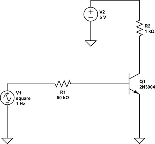
Given your new enhanced description, you should probably be using DIGITAL TECHNIQUES to look for falling edges on your 9V chopped signal. Use the signal to drive the base of a transistor, and a fairly big resistor to current limit that. Power the transistor with 5 Volts.

An optocoupler needs to suck enough current to drive a photoelement, and will probably draw more current than a simple transistor circuit.

Detecting your falling edges is a much more efficient way to deal with all of your issues than sampling of the analog signal.

schematic

simulate this circuit – Schematic created using CircuitLab

If you run this simulation, this is actually inverting, so you would detect rising edges. I used a generic transistor, but a 2n3904 would be fine.

Scott Seidman
  • 29,274
  • 4
  • 44
  • 109
  • This seems to be a great idea! Simpler than buildinga untiy gain OPAmp circuit along with a resistive voltage divider(as I tried to describe in the comment above). Since I want to detect the falling edges, I guess I would need a pnp transistor. Any recommendations, on what value base resistors and which transistors? – Ameya Dec 17 '14 at 19:11
  • @Ameya, I provide an inverting circuit for you in the answer now. – Scott Seidman Dec 17 '14 at 19:56
0

You can use analog or digital inputs, since you don't need to measure the exact voltage, only detect interruptions.

The high value voltage divider as suggested is all you need, for either analog or digital. If you are running your Arduino on 5v, you can just drop the 9V in half. From what you say, you don't really need to worry much about loading the circuit - you'll need far less than the 230 mA it already draws, to make a measurement. For example, two 4.7K resistors will only draw about 1 mA. I might use 10 time that or more tho.

All this assumes your arduino is separately powered, right? You will need to share the ground of the Arduino with the negative side of the 9v circuit.

You may have bigger problems tho - there could be spikes in the 9V line. So you might want to use a small cap across the line, and/or add a reversed diode. But that's not the question you asked - so this is just a heads up.

Zeph
  • 269
  • 1
  • 8