11

I want to convert a \$12V_{AC}\$ power supply output to use \$12V_{DC}\$ to power some outdoor LEDs.

The power supply as it stands will light the LEDs (with a slight flicker from the reverse polarity portion of the AC) but I have been told this may reduce the life of the LEDs having them reverse polarity for a long time.

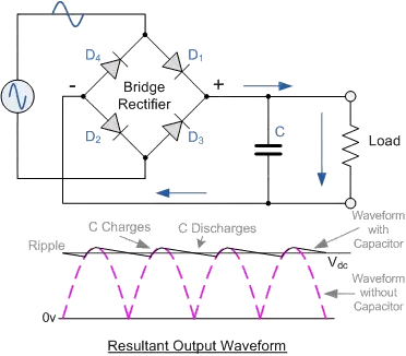
So can someone suggest a simple rectifier circuit I could build or point me in the right direction of which one of these Maplin rectifiers is suitable (I'm not sure what the specifications refer to exactly)?

stevenvh
  • 145,145
  • 21
  • 455
  • 667
Matt Wilko
  • 213
  • 2
  • 6
  • 1
    http://electronics.stackexchange.com/questions/515/how-to-convert-ac-to-dc http://electronics.stackexchange.com/questions/12390/using-a-transformer-to-step-down-230v-to-12v – endolith May 18 '11 at 14:45

3 Answers3

12

You may want to have a look at the answers to this question.

Applying AC to a LED is not a good idea. The flicker is not the main problem (may be hardly visible), but LEDs have a limited reverse voltage, usually about 5V. So the 12V you're using is way too high and may destroy your LED.
What you need is a rectifier, followed by a capacitor (to flatten out the rectified voltage). You can use a rectifier like in your Maplin link, or use discrete diodes.

bridge rectifier

1A diodes like 1N4001 are standard and will do nicely for a few standard LEDs. For the capacitor I use 2000uF/A as a rule of thumb, so if your LEDs consume 100mA you could use a 220uF/25V electrolytic capacitor. Be sure to place the capacitor correctly; it may explode if you reverse it.

The DC voltage will be about 15V (\$12V \times \sqrt{2} - 2V\$ ), so depending on the type of LED you're using it's a good idea to place a number of them in series, otherwise you'll have a big voltage drop over your series resistor = less efficient.

stevenvh
  • 145,145
  • 21
  • 455
  • 667
  • Why the -2V volts? Is it not -1.4V since a standard diod is dropping 0.7V? Or did I miss something? – Johan Jul 28 '11 at 07:17
  • 1
    @Johan - the 0.7V is often used as a rule-of-thumb, but in practice the value is often higher. That's because there's a current peak during the short time the diode conducts, and forward voltage rises with current. For a 1N4001 1V is a typical value at 1-2A, which gives us some margin. – stevenvh Jul 28 '11 at 07:25
  • @Johan - According to [this datasheet](http://www.diodes.com/datasheets/ds28002.pdf) the 0.7V is valid for a current of only 10mA. – stevenvh Jul 28 '11 at 07:48
  • That is very interesting, did not realised that it was so load dependent. – Johan Jul 28 '11 at 09:45
  • Wouldn't a series diode be enough for this application? (With a capacitor of course) – clabacchio May 24 '12 at 13:46
  • @clabacchio - could be. My guess is that the extra size in capacitor will outweigh the extra diodes, esp. if you would use a [single](http://www.digikey.com/product-detail/en/G3SBA20-E3%2F51/G3SBA20-E3%2F51-ND/2139771) bridge rectifier. – stevenvh May 24 '12 at 13:58
3

You don't need a rectifier. The problem is that the LEDs are exposed to too much reverse voltage, conversion to 12VDC is only one solution. You can drive the LEDs with AC voltage as long as you implement some circuitry to minimize their reverse voltage.

This can be done with a single additional diode in one of three ways:

  1. Place the diode anti-parallel to the LED, such that it conducts during the negative half cycle. This drops the reverse voltage to 1V or less, which the LED can handle easily.
  2. Place a second LED anti-parallel to the first one. This allows the LEDs to conduct alternately on the positive and negative cycles. If efficiency is a concern, this is better than method 1, because power is dissipated as light rather than heat from the standard rectifying diode. The reverse voltage seen by either LED will be equal to the forward voltage. Check the datasheet, this may or may not be OK.
  3. Place a rectifying diode in series with the LED. The leakage current of the LED under a reverse-biased condition is much greater than that of the rectifying diode, so the voltage across the LED will be low. This saves power by not conducting during the negative half-cycle, but decreases the light output. You may have to increase the current to compensate.
Kevin Vermeer
  • 19,989
  • 8
  • 57
  • 102
1

A neater solution would be to put a standard rectifier diode (such as the 1N4001 as mentioned) in anti-parallel with the LED, this would conduct in the negative half cycle therefore exposing the LED to only a small reverse bias of about 1 volt.

BullBoyShoes
  • 928
  • 4
  • 5
  • 2
    With this approach the LED on-time is going to be less than 50%, which will make it appear dimmer than the bridge rectifier solution (which effectively applies double the line frequency to the LED, doubling the on-time). – Adam Lawrence Jul 27 '11 at 20:43
  • @Mad - But you can increase the forward current to offset this problem: Power dissipation is an averaged quantity. Some say that a plused LED appears brighter than one run at the maximum continuous current with the same power dissipation. – Kevin Vermeer Jul 28 '11 at 00:46
  • @Kevin - that's not correct. Intensity increases less than linearly when current is increased. So for instance 10% duty cycle pulses at 10x the current will not result in 10x the intensity during the pulse, and therefore on average also less bright than with continuous current. – stevenvh Jul 28 '11 at 07:09
  • Well if you put a big capacitor after the diod you would get a half wave rectifier. And then you would probably not get any visual flicker. – Johan Jul 28 '11 at 07:12
  • @stevenvh: (1) I didn't claim that intensity was greater. I stated that the apparent brightness to the human eye (a subjective measurement) is greater. (2) WRT linearity, [these](http://i.stack.imgur.com/3DHeZ.png) [graphs](http://i.stack.imgur.com/MqSQO.png) (from [these](http://www.us.kingbright.com/images/catalog/SPEC/APT3216SECK.pdf) [datasheets](http://www.kingbrightusa.com/images/catalog/SPEC/AA3535SEL1Z1S.pdf)) would disagree. The first is linear as best I can tell, and the second is nearly linear over three decades. – Kevin Vermeer Jul 28 '11 at 13:50
  • @Kevin - I'm a bit surprised at the graphs; the first one is definitely linear. I've seen graphs that show less linear behavior; I didn't claim it wouldn't increase at all though. Our eye is not very sensitive to small changes in intensity, intensity has to be a lot higher before brightness increases noticeable. Apparent brightness is logarithmic with intensity. Bright sunlight is 1000x more luminous than a dimly lit room, but the difference doesn't appear to be so big. Anyway, what do others think about apparent brightness above 20mA? – stevenvh Jul 28 '11 at 14:12
  • @stevenvh (and, potentially the 'others' who are interested in this stuff): This is getting a little off topic. [New question here!](http://electronics.stackexchange.com/questions/17528/does-pulsing-an-led-at-higher-current-yield-greater-apparent-brightness) – Kevin Vermeer Jul 28 '11 at 14:43