11

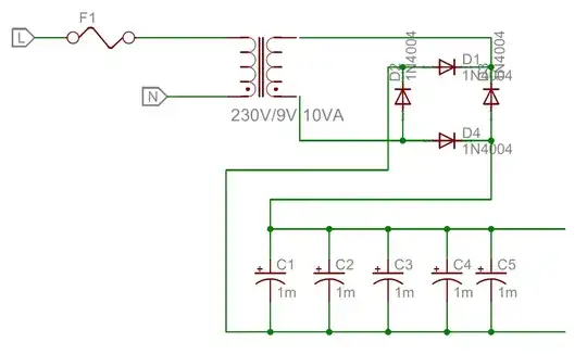
I'm making a power supply using a transformer and bridge rectifier, and I'm wondering whether it is a bad idea to put multiple (5) capacitors in parallel for smoothing.

The output should be capable of drawing 1.1A at 10.7V. I'm allowing for a ~2V peak to peak ripple, as this is fed into a boost converter.

$$ C = \frac{I }{2 f V_{p-p}} $$

$$ = \frac{1.1 }{100 *2} $$

$$ = 5.5mF $$

Further, what if I was to use different valued capacitors (e.g. a 4.7mF and 1mF)? enter image description here

tgun926
  • 2,726
  • 12
  • 36
  • 59
  • 5
    Multiple capacitors of different values are often used for filtering out different frequencies. Multiple together like that act almost like a single capacitor, so no problem. Adding more smaller capacitors (100nF, 1nF, etc) can clean up other higher frequency noise. – Majenko Dec 11 '14 at 00:12
  • @Majenko I have seen this all the time on schematics, but I always thought it was to reduce ESR. Why wouldn't the larger cap get rid of HF noise? – tgun926 Dec 11 '14 at 00:30
  • 2
    Reducing ESR is one effect, yes. As for frequencies, google "capacitor self resonance". – Majenko Dec 11 '14 at 01:21
  • 2
    Take a gander at http://electronics.stackexchange.com/questions/3879/frequency-dependence-of-electrolytic-capacitors for some more insights related to frequency response of real capacitors – vicatcu Dec 11 '14 at 01:48
  • 7
    Also, check the polarity of your diodes. – Simon Richter Dec 11 '14 at 02:14
  • @SimonRichter Cheers for that! – tgun926 Dec 11 '14 at 04:59
  • From the circuit diagram provided, it seems to me that the bridge rectifier is wrongly connected. In a bridge rectifier, the point which vomits-out DC-Positive charges, the 2 adjascent diode's cathode (arrow-head of symbol of diode) should be attached. and the point which sucks-in the DC-positive (i.e. the terminus which gives us negative charge); the 2 adjascent diode's anode (back of the arrow of diode symbol) should be attached. It seems from the diagram, the bridge is connected in the reverse way. – Always Confused Jun 02 '16 at 12:23

3 Answers3

15

It is common practice to parallel a bunch of capacitors of small values for noise suppression; each value suppresses a different frequency band. The values are typically provisioned in decades, e.g. 0.001µF (1nF), 0.01 µF (10nF), 0.1 µF (100nF) etc. For high-frequency devices like cell radios, you will see caps in the pF range.

However it is also common to parallel capacitors of higher values, either electrolytic or tantalum. This is done for several reasons. First, the value you want may not be available, but a smaller value that can be paralleled is. Or maybe the larger value isn't available in the tolerance you want, and again you can get that in a smaller value.

Then there are price considerations. Depending on a how common the value is, a larger value cap may actually cost more than twice what two smaller caps cost.

And finally, there are size considerations, particularly on a board with SMT devices. The manufacturer recommended adding 2000µF to a 3.6V rail going into a cell module. First of all, a single 2000µF tantalum cap wasn't available, just 2200µF. But it was actually bigger than two 1000µF caps, and cost more than the two smaller ones together. So I used two 1000µF capacitors.
JYelton
  • 32,302
  • 33
  • 134
  • 249
tcrosley
  • 47,708
  • 5
  • 97
  • 161
  • 1
    And finally (2) you can place each capacitor close to different loads, to reduce impedance due to track length. Of course this depends on physical layout. This is also done with small 100nF'ish decoupling caps near (logic) IC's. – jippie Dec 12 '14 at 16:44
  • 1
    An additional consideration from the "size" perspective is that many products are constrained in one or two dimensions but not all three. A product that needs to be long and slender might have room for a hundred 100uF caps but not have room for even one 220uF cap. – supercat Jan 20 '15 at 18:03
6

No, it's not necessarily bad. A couple good reasons would be to get a form factor that fits (at some expense in total volume) or to get a higher ripple current rating. A bad reason would be to get the exact value you calculated- the tolerance is usually -20%+80%. In this case you can consider 6.8 or 10mF.

Spehro Pefhany
  • 376,485
  • 21
  • 320
  • 842
1

It is not "bad" to connect several smaller capacitors in parallel to make a larger capacitor (it is actually good). If size, volume, price, etc. need not be considered, then you are free to meet the required capacitance with any number of smaller capacitors (with appropriate voltage rating) that add up to the required capacitance.

Guill
  • 2,430
  • 10
  • 6