How can I filter a DC offset of a pulse train with an RC circuit? The signal is a pulse jumping between 3.07V and 3.53V. But I need a pulse which is jumping between 0V to 0.5V. How can I filter that 3V DC offset?
Asked
Active
Viewed 1,540 times
1
-
You need a high-pass filter, http://en.wikipedia.org/wiki/High-pass_filter – diverger Dec 05 '14 at 13:46
-
Be aware that a high pass filter may not work. Depending on the nature of the pulse train it may change pulse widths as the average DC level changes. Look for "DC recovery circuit" or "diode clamp" circuits as alternatives, or use a level shifter instead. – Dec 05 '14 at 13:52
-
Yes, if the duty is variable, a simple RC may not enough. – diverger Dec 05 '14 at 13:53
-
Level shifting is your best bet. See this related question: http://electronics.stackexchange.com/questions/37095/level-shifting-a-2-5v-signal-to-0-5v – akellyirl Dec 05 '14 at 13:53
-
I need the frequency of the pulse. What I understand from your words it is possible to use RC but it will effect the frequency of the pulses? – user16307 Dec 05 '14 at 13:57
-
@user16307: If you just need to remove the 3V DC, then try akellyirl's link. – diverger Dec 05 '14 at 14:01
-
By most definitions, a pulse train of 0V and 0.5V still has a DC offset, somewhere between 0V and 0.5V depending on the duty cycle. – Phil Frost Dec 05 '14 at 15:39
2 Answers
8
The simple and obvious answer that meets your specs is:
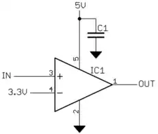
This thresholds the input around the midpoint of what you say the high and low levels are. In practise a little hysteresis is probably wise:
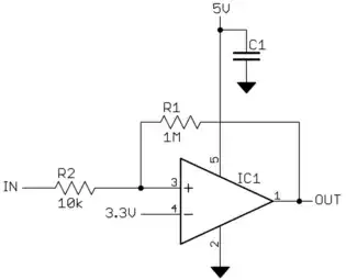
This will create about a 50 mV hystersis band. For example, when the input goes high so that the output goes high, the input has to go 50 mV lower before the output will go low. The hystesis band will be a little assymetric due to your threshold of 3.3 V not being in the middle of the output. This can be compensated for several ways, including adjusting the reference voltage fed into the negative input. Let me know if you want to get into those details.
Olin Lathrop
- 310,974
- 36
- 428
- 915
-
1I think the OP wanted the output to be 0V and 0.5V, but this looks like it would output 0V and 5V. – Phil Frost Dec 05 '14 at 15:37
-
0 to 5V is actually better for me, since I was planning to amplify it. – user16307 Dec 05 '14 at 15:50
-
I will count the pulses. Do you think I need to think about 50 mV hysteresis band issue? What farad is C1? Can I use LM324 which is the only op-amp I have currently? – user16307 Dec 05 '14 at 15:53
-
@Phil: Oops, I missed the decimal point before. Turns out the OP apparently wants more anyway, so I won't update the answer, although a voltage divider on the output of the above circuits could address the issue if 0 - 500 mV was really wanted. – Olin Lathrop Dec 05 '14 at 18:12
-
@user: C1 is just a bypass cap, around 1 uF ceramic. LM324 should work well enough assuming your signal is within its bandwidth capabilities. – Olin Lathrop Dec 05 '14 at 18:14
3
Use an op-amp to create a mixer circuit and subtract the 3.07 volts from the signal: -
V1 can be your input and apply -3.07 volts DC to V2. If you want to restore the polarity of your signal (because Vout = -(V1+V2)) use an op-amp inverter afterwards.
If the dc offset is slightly moving with respect to the signal then something like a data-slicer would work: -
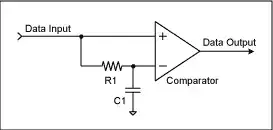
This uses a comparator and one input has the signal plus offset and the other input has the much-slowed-down version of the raw input. This slowed-down version will contain hardly any signal but just the average level of the signal. providing the mark-space ratio doesn't get excessive i.e. greater than 95% or less than 5% then it will produce a logic-level version of the desired digital signal. This can be returned to the 46mVp-p level should that be desired by using a resistor attenuator.
Should the undesired DC offset be wobbling quite a bit then you can use peak detectors on the upper and lower bounds of the composite signal to set upper and lower thresholds for two comparators and get even better performance - the two comparators can set and reset a flip-flop to restore the original signal.
Alternatively, you can use a high pass filter to largely differentiate the composite signal leaving no dc offset and spikes. The spikes will rise positive for edge transitions that were positive and there will be negative spikes for negative edge transitions of the composite signal. Then use a comparator with hysterisis to convert this back to a logic-level signal.

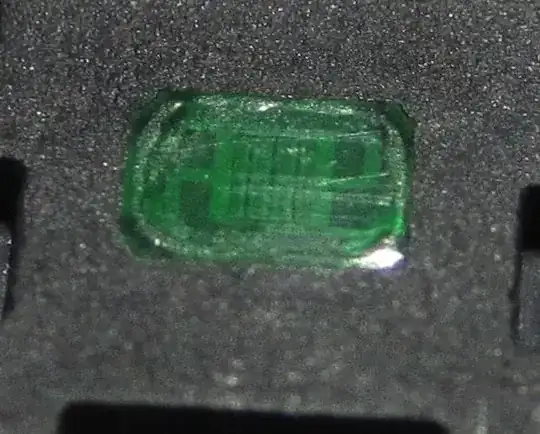
(source: expeyes.in)
If red signal is fed to a comparator with some hysterisis it will toggle the comparator each time a pulse/spike rises above the comparator threshold thus resoring the sq wave. Ignore the scales on the picture above - they are not important but the concept is.
Glorfindel
- 1,245
- 3
- 15
- 20
Andy aka
- 434,556
- 28
- 351
- 777
-
The frequency of the pulses will not be more than 400 Hz. Any suggestion on type of op-Amp? – user16307 Dec 05 '14 at 14:00
-
@user16307 virtually any op-amp would work - it needs to run from at least +/- 5V suppies and should have a bandwidth that is suitable to not cause significant sluggishness to the rise and fall-time of the signal - probably an op-amp with a gain bandwidth product of 1MHz or greater will be fine. – Andy aka Dec 05 '14 at 14:06