3

I've got a PC microphone that fires off a loud pop when muted. Upon taking it apart it appears that its mute circuit is really simple and therein may lie the issue. I've combed this board for fixes and and can't find one. There is this page on the web. The fix seems intuitive but it involves the internal circuit, which is beyond the scope of the mute button; it's inside my sound card and I'll be damned if I have to get in there to fix this. Furthermore, that fix involves a 3 lead mic, where mine is 2. I figure there's clean way to kill this pop without changing (much) the impedance or voltage going to the electret mic.

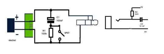
Please see exhibit A: Exhibit A

This seems to be all the involved circuitry of the microphone (Style #1 is its original form).

I figured I could try bridging the ground to the signal upon muting, so I shorted the 2 points in Style #2. This only increased the pop seen on the audio end of the business (audio is mic signal. Mic is open and working then at red line is turned off).

Any suggestions as to how to quell this pop? Many thanks in advance for your time and consideration.

P.s. Ideally, I would like to add a band pass filter for 60hz hum and high-end static. If I'm going to be wiring up more resistors and capacitors for the filter, couldn't 2 birds be killed with one stone?

Bob Ablah
  • 33
  • 1
  • 3
  • I'm not understanding what your mute circuit comprises. – Andy aka Dec 04 '14 at 19:26
  • @Andyaka Sorry to leave that out. There's a carriage (the solid grey lines) that physically slides to the left and right. When it's right, it's bridging the right and center leads, as with the dotted line. When it's left (on) it's bridging the left and center leads. There is no bridging from the top and bottom leads on the carriage. – Bob Ablah Dec 04 '14 at 19:59
  • There are ICs such as the [MAX9892 and MAX9890](https://www.maximintegrated.com/en/design/technical-documents/tutorials/4/4449.html) which are designed specifically to eliminate pops/clicks from audio circuits. – spuder Oct 18 '22 at 14:35

2 Answers2

5

I think you've misinterpreted the circuit shown on the web page. It applies to any electret. Basically it shorts out only the AC (signal) by using a large capacitor but avoids switching the DC bias voltage which is the source of the pop.

enter image description here

When the mic is plugged in C1 experiences a step voltage (from the 5V supply/R2) which brings both terminals of the capacitor to the DC bias level of the electret.

The negative terminal of the capacitor then discharges through R1 (100k) back to (nearly) 0 volts leaving no voltage across R1 (after more than 5 time constants). From the microphone's perspective it 'sees' a parallel load of 100k (the impedance of the large capacitor being negligible). This is so large it has no effect on the mic's output.

When the mute switch is operated (closed) there is no large DC step because the voltage across R1 is 0V and hence no large POP. The microphone now 'sees' only the 100uF capacitor as a load because the 100k has been shorted out. This effectively shorts out any AC (signal) and hence mutes the mic. The DC bias circuit (R2) is not shorted out because C1 is effectively an open circuit to the DC signal.

JIm Dearden
  • 18,926
  • 30
  • 40
  • Thanks for explaining this JIm! This now mostly makes sense to me. I'm going to test this guy out empirically... – Bob Ablah Dec 04 '14 at 21:08
  • So this works well! I've played with different values for C1/R1 and can't quite grasp why this works without R1. The resistor is to bring the - pole of the capacitor to zero volts, right? In my experiments it seems to have the same non-pop effect with/without R1 in the circuit, just leaving C1's - pole at -5v. What am I not understanding about R1's purpose here? – Bob Ablah Dec 11 '14 at 18:04
0

"When the mic is plugged in C1 experiences a step voltage (from the 5V supply/R2) which brings both terminals of the capacitor to the DC bias level of the electret."

i.e. the cap C1 is charged up to the bias voltage of the PC microphone, since R1 is in series with it, it limits the charge rate (and discharge rate) and softens what would be a very abrupt level change or "spike"

"the capacitor then discharges through R1 (100k) back to (nearly) 0 volts leaving no voltage across R1"

R1 bleeds off whatever DC voltage is left on the cap C1.

When you plug the mic in, the audio circuitry sees that as a level change, which it will amplify as a noise spike. If you put a cap across the line, it absorbs that spike, but if you don't bleed the cap, it will effectively behave as though there is no cap at all once it is charged (or until it bleeds naturally over time) But since you have R1 there, it has some place to bleed. If the switch is closed and the mic is unplugged, it will simply power the active circuitry of the electret mic and bleed anyway. The resistor is there for when the switch is open, and therefore gives the cap a path to discharge.

I would say if you left the switch open, took out the resistor, and plugged and unplugged the mic quickly, you would still get popping.

R1 is your friend :)

Ryan
  • 1