1

I'm looking for a little help with regards to the logic required for a project I'm looking at undertaking soon.

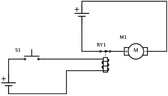
I am looking at creating a 'quickshifter' for my motorbike. The way this will work is by breaking the ignition circuit(signified as M1 motor) momentarily using a 'normally closed' relay(RY1).

The problem I am facing is that the circuit will stay broken for as long as the switch (s1) is pressed. I am looking for a solution that will only leave RY1 open for a specific amount of time, in the 50-100ms range.

I would like the circuit to be broken for a maximum of 50-100ms; this is regardless of how long the button is held down. So for example. If I press and hold the button/switch, the relay will be trigged within the first 50-100ms, but not again until the switch/button is de-pressed and re-pressed.

What logic could be used in order to achieve this? Apologies for my incredibly crude diagram.

extremely basic diagram

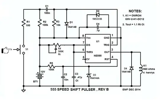
EDIT - I have tried to create a monostable 555 circuit as suggested, but I think I am missing something.

docircuits test example

When I view data recorded when I run the circuit, I see some erratic current readings at Imeter1; and VMeter1 shows the voltage droping from 12v to 0v when the switch is activated.. nothing gets recorded across any other the other meter(IMeter0). Can anyone tell me what I've missed? Am I being an idiot?

Jack
  • 11
  • 1
  • 4
  • 1
    Use monostable circuit like 555 – R Djorane Dec 04 '14 at 14:07
  • see the link: http://www.instructables.com/id/555-Timer/step3/555-Timer-Monostable-Mode-Circuit/ – R Djorane Dec 04 '14 at 14:14
  • @Jack: 1. The lamp doesn't need to be grounded, but the wire connecting C1, C0, Relay0 coil-, and Relay0 armature do. Also, SW0 NO needs to be grounded, 555 pin 3 needs to be connected to the switch as shown on my schematic, and SW0 needs to be debounced when it's opened. Finally, you can get rid of C0, but you need 0.1µF dirctly across 555 pins 1 and 8. – EM Fields Dec 05 '14 at 13:32

3 Answers3

2

This is a simple task for a small microcontroller. Even the tiny PIC 10F200 can do this easily.

The switch pulls a input line to ground. When the micro sees this, it energizes the relay for 100 ms or whatever you decide is the right time. It then goes into a loop waiting for the input line to be high continuously for 100 ms (to debounce the switch and ignore short glitches and prevent rapid back to back firing of the relay), then looks for a new high to low transition of the input line again.

Olin Lathrop
  • 310,974
  • 36
  • 428
  • 915
  • it seems a little complicated for what he's looking for, i think if he use a monostable circuit with his push button SW1 it's will be OK with the appropriate values. – R Djorane Dec 04 '14 at 14:49
  • 1
    @codo: "Complicated" is not a single scalar quantity. Your circuit will be more complicated, but with a micro you have to write code. It depends on the relative importance of different criteria, which the OP hasn't supplied. – Olin Lathrop Dec 04 '14 at 15:03
  • Hey - thanks for your suggestion. I thought I'd better add some more criteria so that you're able to tell me if your suggestion would be suitable. I would like the circuit to be broken for a maximum of 50-100ms; this is regardless of how long the button is held down. So for example. If I press and hold the button/switch, the relay will be trigged within the first 50-100ms, but not again until the switch/button is de-pressed and re-pressed. Does that make sense? – Jack Dec 04 '14 at 15:13
  • @Olin Lathrop: Yes you're right, but for first time we choose the simple solution. – R Djorane Dec 04 '14 at 15:17
  • @Olin: Complexity is, indeed, a vector quantity and, at the end of the day, a PC, an editor of some sort, an assembler, a linker, a programmer and a rather steep learning curve traversed in order to get the job done all have to be added up on the one side. On the other side, adding up reading a schematic and connecting up a handful of discretes sure seems easier. Especially since reading a schematic and doing some wiring is also part of the first part. – EM Fields Dec 04 '14 at 18:28
  • @Jack: Yes, as I said, this method can certainly do what you specify. The accuracy will be that of the oscillator running the micro, which is a few percent for the built-in oscillator of a PIC 10F200. This is a trivia thing for someone familiar with micros to do. Whether you are, or want to learn anyway, you haven't said. – Olin Lathrop Dec 04 '14 at 18:36
  • 1
    @EMFi: As has already been said, each approach can be judged more or less complex, depending on the relative weights of criteria we don't know. For example, if the OP is already familiar with PIC 10Fs and has the development system all set up, then this is a simple task. If not but he would like to learn such things, then this becomes a advantage over using outdated methods. Again, trying to argue "complexity" in this context is just hot air since we don't know the relative importance of various criteria. He asked, I said how I'd do it. It's up to him to judge which approach he prefers. – Olin Lathrop Dec 04 '14 at 18:42
  • It seems rather obvious to me that if the OP was set up to do MCU development at any level, and wanted some help with the code, that's what he would have asked for. As it was he asked for hardware help, which you certainly didn't offer but were more than willing to try to get him to hitch his wagon to your star. As far as your pejorative "outdated methods" crack goes, it has no place here and you should be ashamed of yourself for trying to play the guilt card. Finally, arguing "complexity" is far from hot air, but you pooh-pooh it because you hate losing and you don't have a leg to stand on. – EM Fields Dec 04 '14 at 19:09
2

This'll work for you: enter image description here

and if anyone wants to play with the circuit, the LTspice simulation is here.

There's a 1 second delay built into the sim, just because, but in the circuit above, as soon as S1 is pressed, K1 will go hot and stay hot for 1.1RtCT, no matter how long S1 stays made. Then, when S1 is released and pressed again, U1 will make another single pulse.

Just as an aside, Ct is 0.47µF, so for U1 OUT ~ 100 milliseconds, Rt needs to be 200k ohms, which is about halfway around R4, a rheostat-wired 500k pot.

EM Fields
  • 17,377
  • 2
  • 19
  • 23
  • Wonderful, I was hoping someone would post a 555 thing! – George Herold Dec 04 '14 at 18:52
  • As far as switch de-bouncing, the traditional method is with a SR flip-flop. Another IC... you can get away with an artfully chosen RC thing too. (RC time longer than the bounce time, but not too long.. well unless there is some hysteresis on the input.) – George Herold Dec 05 '14 at 13:58
  • Tell and show? The sim is out there, just waiting... – EM Fields Dec 05 '14 at 14:24
  • Here are some images, https://electrosome.com/switch-debouncing/ (Will you forgive me if I'm too lazy to plug those into your simulation?) – George Herold Dec 05 '14 at 14:54
  • 1
    There's nothing to forgive; I have no expectations of you, one way or the other. – EM Fields Dec 05 '14 at 19:35
  • Looks great. Going to be building a prototype of this tonight. Thanks @EMFields – Jack Dec 08 '14 at 15:13
  • Hey @EMFields - I've had a go at creating a PCB with your design. Can you tell me whether or not this is 100% right? From what I can tell it should work, but you'll know more about bet practices than me. I have replaced K1 with M1 for my example..; http://pixxl.us/i/HsZn.png – Jack Dec 09 '14 at 11:04
  • It seems there was some confusion about the 555's pinout and, as a consequence, it's shown on your layout wired dead-bug. I added the 555 pinout numbering to the drawing to make it clearer. There are other errors on the board, like C4 is missing and, according to U1's orientation, pins 6 and 8 are connected. There may be more, but I stopped there. – EM Fields Dec 09 '14 at 14:25
  • @Jack: RevB: Change R1 to 100k and C1 to 100nF for better S1 bounce reduction. – EM Fields Dec 09 '14 at 23:56
  • @EMFields - thank you for your continued help! You might be able to tell, but I've only got beginner level knowledge with this. I've recreated your diagram from scratch in Fritzing, this time I was much more careful with my breakpoints and pin orientation. Could you scan over this PCB design and tell me if you see any obvious mistakes? I understand my layout might be really untidy, but I'm unaware of which 'best-practises' to work by. http://pixxl.us/i/nzr5.png – Jack Dec 10 '14 at 13:27
0

Well I assume you are powering everything from 12V. So it would be nice to have an IC that works up there. As other's said in the comments this looks like a perfect job for a one-shot/ monostable. Perhaps a 555, but I was going to suggest something from the CMOS 4000B series. Perhaps the CD4047. And though this will most likely send Olin spinning, I'd get sometihng in a dip package. Easier to solder to and prototype. (Here are my hit's from Digikey.) Oh, you will most likely need a little more current than the IC can provide to operate the relay. So a transistor current gain circuit may be needed.

George Herold
  • 4,754
  • 1
  • 18
  • 25
  • Hey @George - please see my comment on Olin's answer - do you think your solution could account for this? – Jack Dec 04 '14 at 15:28
  • Hi Jack, It's been a long time since I last used a one shot. (circa '95) Want you want is possible. I'm not sure the 4047 will do it.. I'd (You'd) have to read the spec sheet. What might be a bigger issue is debouncing your switch. When you turn your switch off there may also be some pulses generated.. that would be bad. Perhaps someone will post a 555 circuit that will work and that will be better for you. – George Herold Dec 04 '14 at 15:46
  • @GeorgeHerold: The bipolar 555 is specified to work with a Vcc of from about 3V to 18V, so that's not a problem. The 4047 can only source or sink about 2.5 mA with a 15V supply, so that's a **big** problem if it's trying to drive a relay. That problem is solved by using a 555, which can source/sink about 200 mA. Also, debouncing isn't a problem with either chip since its output will go high and stay high for the entirety of the bounce period. If the bounce lasts for less than the output period, that is. – EM Fields Dec 04 '14 at 16:44
  • @GeorgeHerold: A problem I hadn't anticipated, but which I think you noted, is that if the switch is held closed for longer than the one-shot's timeout and then released, the bounce on release could cause the one-shot to trigger. As you said, that would be bad. – EM Fields Dec 04 '14 at 23:44
  • @EMFields, yeah and the automotive enviornment. I'm thinking decoupling of the power supply will be important, but I've never done automotive design. – George Herold Dec 04 '14 at 23:53