5

schematic

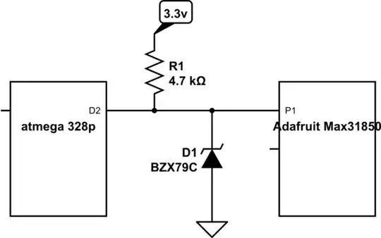
simulate this circuit – Schematic created using CircuitLab

My problem is the ATmega328 is running at 5V. I know I need a bidirectional level shifter. However don't really want to spend much more money on this if I can. I don't want to blow up an expensive amplifier as well. Most expensive IC I've ever bought.

The D2 pin would output 5V but I thought zener diodes are commonly used for over voltage protection. So why I can't just use this diode to clamp it down to 3.3v? I know I need bidirectional level shifting but wouldn't the voltage be clamped to 3.3v either way?

John Honniball
  • 2,799
  • 11
  • 10
Ageis
  • 3,311
  • 13
  • 44
  • 67
  • 3
    See the n-channel MOSFET solution at http://electronics.stackexchange.com/questions/16783/bidirectional-level-swiching-5v-3-3v?rq=1 - but first check data sheets to make sure everything just won't work by pulling high to 3.3V and setting the atmega to open drain – Scott Seidman Dec 03 '14 at 15:35
  • How about just a resistor voltage divider? – George Herold Dec 03 '14 at 16:48
  • 1
    Use the MAX31855 instead and make your life 10 times easier. – whatsisname Dec 03 '14 at 18:12
  • 1
    Any reason you can't just run the microcontroller at 3.3V? –  Dec 03 '14 at 18:49
  • yes I selected the pro/ pro mini to 3.3v @8mhz bootloader and it successfully flashed. HOwever when I tried upload a sketch it failed with "not in sync error" however I change nothing except power my ftdi vccio (logic level voltage) from 3.3v to 5v then it works. It seems it doesn't like 3.3v – Ageis Dec 03 '14 at 23:04

4 Answers4

10

Upon looking at the data sheet for the max31850, it looks like you want to connect an open-drain 3.3V output (or input) to a 5V input (or output when low).

I don't think this is a good idea to use a zener- the knee is too soft, and the output driver of the max31850 is too wimpy (4mA) to make this work reliably. Also the minimum voltage to be recognized as a 1 is 0.6 Vdd, which is 3.0V, a bit too close to 3.3V for comfort when working in the reverse direction- the zener will be conducting significantly at that voltage. Further, the datasheet typical capacitance for the zener is 450pF at 0V (more when forward biased) so you may not get the speed.

The Zener would draw excessive current from the micro if the port pin was driven high accidentally (and would likely exceed the maximum voltage spec), and the 4.7K plus the zener soft knee would likely lead to 'high' voltages that were not enough to guarantee operation. Generally all bad news.

enter image description here

Powering the ATMega from 3.3V would make these problems go away.

Spehro Pefhany
  • 376,485
  • 21
  • 320
  • 842
  • 2
    thanks alot!! I've learn't something from your answer. Next time I'll know to look at how strong the output driver is! Also learnt some technical speak "the knee is too soft". Makes me sound as though i know what am talking about. – Ageis Dec 03 '14 at 16:12
5

That configuration is asking for trouble. The 328, when driving a high output, is rated for ~ 4 volts @ 20 mA, so it will be way outside its comfort zone when driving a 3 volt zener. Instead, run a 200 ohm resistor from D2 to the zener, and a 1k from the zener to P1.

Another possible problem with your idea is speed. You don't say how fast you want the lines to toggle. A 3-volt BZX79C has a capacitance around 470 pF. Combined with the 4.7k resistor you've shown gives a time constant of about 2 microseconds, so you could not reasonably expect data transfers at greater than 100 kHz. With the components I've suggested, you can get about 500 kHz from the Adafruit.

WhatRoughBeast
  • 59,978
  • 2
  • 37
  • 97
  • I would think adding a Schottky diode in series with the resistor could improve speed even further; in its absence, falling edge transitions would be slower than rising ones (the resistor would have an extra 1.7 volts [the difference between 5 and 3.3] across it on a rising edge). – supercat Dec 03 '14 at 16:12
3

You're thinking along the right lines with the zener, but you have the resistor in the wrong place. Do not build this circuit! The resistor should be in series with the signal line, between ATmega328 and diode.

Have a look at this very similar question:

How does a zener protect my microcontroller?

You're right that a zener circuit will work for a bidirectional signal line. The output voltage from the MAX31850 will not exceed 3.3V, assuming that it's a 3.3V chip.

John Honniball
  • 2,799
  • 11
  • 10
  • John, JUst to clarify it's the microcontroller that's the problem it's 5v and it says 3.3v only on the silkscreen of the breakout for the max31850. It's in some weird smd package with tiny tiny pins. Also The resistor was meant to be a pull up for the data line. It's uses maxim one wire protocol. – Ageis Dec 03 '14 at 15:26
  • @Ageis OK, yes, the ATmega328 is the 5V chip. It's not a "weird" package, just a small one! You're right, you'll need another resistor for the pullup (to 3.3V) if it's a one-wire signal. – John Honniball Dec 03 '14 at 15:47
1

For usage of zener diode, both @JohnHonniball and @Spehro have good suggestions. But I think you may not need zener diode.

Per MAX31850's datasheet, MAX31850 have 4 pins, DQ for data output, open-drain and read-only. AD0~AD3 for address input.

As DQ pin is read-only, so you only read it. And atmega328 can recogonize 3.3V as a logic high (when \$V_{CC}\$ = 2.4V ~ 5.5V, \$V_{IH(min)}\$= 0.6\$V_{CC}\$ ). So you just need configure your data pin as a input, then it won't output high voltage. Don't forget put the 3.3V pull-up resistor.

For address pins, because they are basically input only pins. If you need them be MCU controlled, you can use simply resistor dividers. If you don't need MCU controlled address, you can just fix them to some voltage, per the datasheet.

diverger
  • 5,828
  • 5
  • 43
  • 79