1

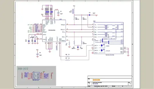
Referring to this schematic, what do the little white circles with red lines mean in the pin out diagram?

schematic

Nick Alexeev
  • 37,739
  • 17
  • 97
  • 230
sholsapp
  • 217
  • 2
  • 8

1 Answers1

6

The circle at a pin location of a digital logic chip indicates that the signal is active low rather than active high.

Ignacio Vazquez-Abrams
  • 48,282
  • 4
  • 73
  • 102
  • If I'm programming with GPIO, would I use a pull up or down configuration for these types of pins? – sholsapp Dec 03 '14 at 05:54
  • That question is unanswerable without context. – Ignacio Vazquez-Abrams Dec 03 '14 at 05:56
  • Can you help me understand why not, and what context I can provide to help answer the question? – sholsapp Dec 03 '14 at 05:58
  • Because it completely depends on what the pins are, what they do, and how they work. – Ignacio Vazquez-Abrams Dec 03 '14 at 05:59
  • I'm still not sure what context you will need, but I'm trying to discover if the problem I'm experiencing in http://electronics.stackexchange.com/questions/140299/are-all-connections-to-my-enc28j60-required/140373 is because I have my SPI pins misconfigured (viz., that they're not using the correct PULL-UP vs. PULL-DOWN setting). – sholsapp Dec 03 '14 at 06:01
  • You have to refer to the IC data sheet to determine whether that GPIO pin has the full push-pull output structure inside the microcontroller, or just has the open-drain output structure. If it's open-drain then it would require an external resistor to pull up to the logic high level when the GPIO is not being actively pulled low. – MarkU Dec 03 '14 at 06:02
  • SPI connections are actively driven and so don't need either by default. – Ignacio Vazquez-Abrams Dec 03 '14 at 06:03
  • If that GPIO pin has the full push-pull output structure inside the microcontroller, then the microcontroller itself can actively drive logic high or logic low, without requiring an external resistor. – MarkU Dec 03 '14 at 06:03
  • Based on the other question... have you used an oscilloscope to verify that the SPI signals are being driven to valid logic states? – MarkU Dec 03 '14 at 06:06
  • @MarkU I haven't, but I've used LED to verify that at least something is happening on CS, MOSI and a few others. I can't get MISO to produce anything using my janky LED method. I don't have an oscope yet. – sholsapp Dec 03 '14 at 06:08
  • MISO (Master-In, Slave-Out) should be driven by the device, but only during certain times -- it's not likely to make much of an LED light show, assuming the SPI slave device is capable of driving an LED. Microcontrollers often have sufficient GPIO current sinking ability to light up a red LED, but a low-power SPI slave device wouldn't normally be expected to drive that type of load. Check the IC data sheet Electrical Characteristics table for the MISO (DOUT) output driver, VOLmax test condition should list a test current... – MarkU Dec 03 '14 at 06:17
  • If it's less than 5mA then I don't think the LED test will be valid for MISO. – MarkU Dec 03 '14 at 06:19
  • 1
    Sounds like I need an oscope, then. :) Thanks for that tip. – sholsapp Dec 03 '14 at 06:20