5

My water heater element is rated at 3.6kW at 240V. To use solar power efficiently, I would like to use excess solar power (in a grid-tied arrangement) to heat our domestic hot water. Our electricity supplier only pays a pittance for exported power but still charges the full rate on any imported power, so the trick is to control the current to the hot water system (HWS) so that most excess solar power is consumed internally.

Would a heavy duty phase controlled triac be suitable? Would the large current switches cause problems? I do not know how the metering works, so this per-cycle method may not even register as a smaller average current. Ideally, the load should look like a varying resistance.

Would an approach like a switching power supply make sense? ie rectify the AC, then chop the current at high frequency, while protecting the supply side with large filters? I suspect this approach would cause EM noise unless carefully designed.

Are there better ways of controlling HWS power?

Motivation

The inverter connects on my side of the meter, but import and export are measured separately. I am trying to minimise the bill to the electricity company. To do that I need to use as much of the solar generated power internally, while being careful not to import power during a sunny day. Eg: when solar power in = 4kW, internal loads = 2kW, I want the HWS to draw 2kW. If I export power I get 7 cents per kWh. If I import power I pay 20 cents per kWh. The feasibility of the installation hinges on whether I can vary the load to match the generation.
Variable HWS power chart

Logic Knight
  • 496
  • 3
  • 10
  • Relay? SSR? or do you need finely variable control of how much power is dumped into the HWS? – John U Dec 02 '14 at 18:18
  • I guess 500W steps would be workable but I was thinking that full variable should be possible. – Logic Knight Dec 02 '14 at 18:27
  • 2
    Why not heat the water directly from the sun. I've got a system that does that and it works a treat when the sun comes out. – Andy aka Dec 02 '14 at 18:30
  • I think the best way to control the power to your 240V water heater is with a relay or contactor rated for the amount of power. Heater is a resistive load. Look for something with a 5kW rating for resistive loads. I think these types of relays usually require a 24V or higher coil voltage. If you can find one rated for 24V DC, you can control the coil current with some kind of solid state electronics, provided you can supply 24V. The three letter abbreviation used for domestic hot water is DHW, not HWS. At least in my experience. ;-) – user57037 Dec 02 '14 at 18:32
  • Wait a minute, if you are trying to design a system that can modulate power to the heating coil of your hot water heater in real time... Well, that is not going to be easy. But you can ignore my previous comment. I was envisioning you turning the heater on and off for minutes at a time. – user57037 Dec 02 '14 at 18:34
  • @Andy Where is the Electrical Engineering in that ;-) My aim is to justify a roof mounted solar installation by using spare solar power to make 400 litres of hot water. I have daughters. – Logic Knight Dec 02 '14 at 18:40
  • 1
    @mkeith Yes, I need the make the DHW (HWS seems common in Australia) load variable in real time as solar power supply and internal house loads change. I am OK with sensors and controllers but heavy power control is outside my experience. – Logic Knight Dec 02 '14 at 18:45
  • You should also consider what kind of impedance you present to the utility (or grid-tie inverter). If you just rectify the 240V, add a big capacitor, it will be easy to design, and you can probably apply DC or square wave AC to the heating element. But it will be hard on the grid. Anyway, I don't think I can help you. Good luck! – user57037 Dec 02 '14 at 18:52
  • I guess the method you employ would have to depend on how the power gets from the panels to the heater - if there's an inverter in the way, many of the usual methods of varying a load (a-la dimmer switch) might be considered a bit hard on an inverter. – John U Dec 02 '14 at 22:57
  • @John The inverter is grid-connected which means the inverter will not be slammed by rapid current switches, but the noise caused by a switching controller would have to be managed (to be gentle on the grid-sensing part of the inverter and other household appliances). – Logic Knight Dec 03 '14 at 05:27
  • Did you get anywhere with this? – Russell McMahon May 20 '15 at 12:19
  • I could not find any commercial products, existing designs, or any interest from power engineers. There must be a large market for this product. I posted my high level design answer below, but then abandoned my plan in frustration. I would need to spend over 100 hours building this to save $300 per year off my electricity bill. Not worth it. – Logic Knight May 20 '15 at 13:42
  • @carpetpython How did you make out with this? I'm working on something very similar that you might be able to make use of. chmorgan@gmail.com is my email address. – Chris Morgan May 23 '17 at 19:59
  • You should stop trying to convert solar energy to electricity and turn around and try to heat water with said electricity. This is a horribly inefficient process. You should instead use the solar energy to directly heat up the water. This is a whole lot more efficient. – Michael Karas Dec 03 '14 at 02:23
  • Can it be this hard? Have two temperature set points for your geyser. One is set to 65 degC or whatever maximum you are prepared to tolerate. The other is set to 40 degC or whatever minimum you are prepared to suffer. If the sun is shining use the higher temperature limit with only solar power and if the sun is not shining use the lower limit. This will store excess energy in the hotter water when possible but keep it warm enough for daily use with utility power when the sun is not shining. If the sun is shining and the geyser is over 65 degC then have it feed to the grid. – KalleMP Oct 28 '18 at 17:59

7 Answers7

3

Presumably the output of the inverter fed from your solar cells is on your side of the meter. Therefore you don't get charged at all for any power you use up to what the solar panels are producing at the moment. It already works as you seem to be asking.

For example, if your solar panels (thru the ineverter) are producing 1 kW when your 3.6 kW heater is on, then you will only be drawing 2.6 kW from the line, and will only be charged for the 2.6 kW. If the panels are producing 4 kW with the heater running, then 3.6 kW goes to the heater locally, and you are actually dumping 400 W onto the line. The power company can't tell the difference between you having everything off and producing 400 W that's going onto the line, and you producing 4 kW with 3.6 kW used internally and dumping the remaining 400 W onto the line.

There doesn't seem to be a problem here to solve.

Olin Lathrop
  • 310,974
  • 36
  • 428
  • 915
  • "Presumably the output of the inverter fed from your solar cells is on your side of the meter. " ... This isn't the usual arrangement where Feed In Tariffs are involved - these use a meter with two separate inputs and determine net input/output by comparing the usage of each. – Jules Oct 28 '18 at 11:30
2

In general, the power meters measure total power over some interval, and then determine if it was 'import' or 'export' base on the sign of then total value. This interval cannot be too small -- a switcher with no load will have power factor close to zero, and thus 'export' power in one part of AC cycle and 'import' power in another part of AC cycle. It would be stupid for power meter to register it as '40W import + 40W export' simultaneously.

I have no idea what this interval is for your meter; but if it is at least few seconds, you should be doing low-frequency PWM (with period measured in seconds) and using it to control zero-crossing solid-state relay. The 'zero-crossing' part will ensure the lack of extreme currents and EM interference.

Your heater takes (3600 watts) / (240 volts) = 15 amperes. Thus, any 20A / 250V SSR (solid state relay) will work. Also See this question for details:

Switching / dimming a high power mains heater

UPDATE: This document ("Import and export of electrical energy" by "Surendra Jhalora") talks a lot about import/export energy when applied to smart meters: http://www.securetogether.com/files/5113/7291/7734/imp_exp_elecl_energ17.pdf

According to it, the import/export is calculated per-cycle. If it applies to your meter (and we do not known that), zero-crossing SSR will not help.

theamk
  • 3,128
  • 11
  • 15
  • Good point about the metering interval. I will try to find out what this is. If it is more than a few cycles, I could use a SSR to switch some cycles on each period as you have suggested. Thanks also for the useful link. – Logic Knight Dec 03 '14 at 05:22
  • The Jhalora article does suggest the import and export are measured cycle by cycle. I will look into this. Thanks. – Logic Knight Dec 04 '14 at 06:47
2

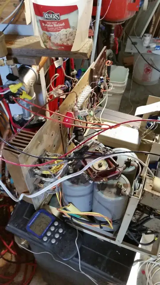
Retired technician, have been working on the same thing for a long time. 6000Watt power electronics SCARE ME. Always test behind a 3/4" plywood shield. It is currently in service and working great(except for horrid RF noise). Glad to share, hope for some help. My set up is a little different. 8000w 230v sine wave inverter(stacked Trace SW4024)(now Schnieder) from the last century. 42kwh agm batteries(salvage). 15+KW of solar panels(mostly vertical on side of buildings, 48.5° N Latitude. So many panels to get thru winter with no generator. Vertical is far best this time of year. max sun elevation is 20° or less. they put out nothing with snow on 'em. Back as far as 1999 I was bank switching sets of panels when the batteries were charged, to 72V to send to hot water tank element. Oh yeh, I'm off grid.

Current setup is: Salvaged 230V input, 54V output at 50amp switching charger frame(2 came with batteries ;-). Using the filtering input as was: About a 2" torroid with bifillar winding from l1 l2 An iron core choke on each line(several pounds each) 4 35amp full bridge rectifiers on large heat sink 4 large(8,000µF 150V) series connected filter caps w/bleed-balance resistors Another 2" torroid with bifillar winding Now my circuit:pwm at 1000hz with a cypress psoc4200 µPC sensing volts from batteries, fet's driven with a 2.5amp opto isolated driver chip and 15dc supplyscarry?. 2 IRFP460 FET's <500v 20a, and only $3.33 ea. quan 10(had 4, 2 blew on first fire up(no pun intended). Tried to look at wave form, but with the ringing on top of the 340vdc it shorted my 10x scope probe(now have a 1500v probe 100x) Have run at 5500watts) large heatsinks never get above 120°F. pwm only slightly over 55% iirc. them caps change things! Fet's are on grd with 4500w element to positive. across fet's is a snubber circuit(here I am very very unknowledgeable) with a 0.1µF cap & a 3.3k 5w resistor(runs extremely hot). There is a 0.1µF cap across the heater element.

The element is in a 1 gallon per minute flow of water to hydronics in a 20cuYd cement slab, my 'thermal battery'. On our rare sunny days it only warms up less than 5 degrees. So many panels because they are so cheap now! $0.27cents/watt ($0.35 w/shipping). Without running generator, I can run propane/solar electric heat for the winter on one fill.

schematic

on the VO3120 opto-isolator K should be A

mtnCbn
  • 29
  • 2
  • 2
    That's great, but at this site its not about about you setup, but more about answering the question, which was about control. Could you edit your question and include a control scheme or schematic? – Voltage Spike Nov 27 '17 at 21:55
  • didn't have a schematic, one is added now(Circuit Labs didn't behave well on my computer. Drew it a 2nd time local & added pic). I tried to give a very accurate control scheme in my text description. Sorry. – mtnCbn Nov 28 '17 at 02:23
  • This is a blog post, not an answer – Chris Stratton Oct 22 '20 at 04:21
1

The variable power controller design is basically on the right track for providing continuously variable output power. There is however a detail that it doesn't address and that is the temperature regulation of the cylinder. As drawn, the controller connects directly to the element without going through the usual thermostatic control. That might be ok if you can cope with boiling the cylinder or tripping the over temperature relief valve. If the thermostat is left in the circuit, its switching contacts won't last long when it starts switching DC voltages over 30 or 40 volts due to DC arcing. The arc quenching advantages of AC quickly disappear when switching DC. To remedy this, the thermostat contacts could instead provide an additional control input to the PWM control to shut it down when the temperature set point is reached. To make the best use of the solar input, the set point could also be set a bit higher, say 70 degrees instead of 55-60. This assumes that the hot water is delivered via a tempering valve to avoid scalding. Bare in mind too that the standing losses from the cylinder go up as it's temperature gets higher.

1

I think I've found a really good workaround solution for this.

I'm trying to do exactly the same thing - use my excess solar power to heat my water. It is a 4,800W heater and I typically have 3,000W of excess solar at maximum for 3hiurss a day. I need to somehow throttle my heater to 1-2kw or so. I've been looking at high power motor controllers, triacs etc.

A more elegant solution:

Put a transformer (or multiple) in series with the heating element, and just switch that/those on/off.

You're 240V, so sounds like my neck of the woods. I have a dual element 4.8kW heater. Check the wiring diagram for your heater, there's a thermostat & all other safety stuff. Don't interfere with that. Just put the transformer between the thermostat & element of what ever size you need, then it is a simple switch on/off via Arduino.

(Check my maths here.)

4.8kW @ 240v is about 12ohms for the element. If I have a 75V transformer it'll pull 6.25A & 468W If I have a 100V transformer it'll pull 8.3A & 830W

So grab a 500W 75V transformer and put that between the thermostat & element, run the element at a lower voltage, which will be a lower power.

tThen just use a ESP8266 equivalent and a solid state relay to turn them on/off.

Maybe do the 1000W transformer and use some PWM/SCR stuff on that - you're controlling much lower power, so everything will be nicely scaled down and less of a hassle.

EDIT FYI - Just picked up an AU to JP transformer, 1000W for $115 - can handle 800W continuous no issues - so that seems the best path. You'd need 1200-1400W for an AU-US step down to give some headroom.

JRE
  • 67,678
  • 8
  • 104
  • 179
Nate
  • 11
  • 2
0

Here is an attempt at a variable power controller design. The circuit rectifies the mains current, then uses high frequency PWM to control current to the heater element through a filter (to limit EM noise).

Variable Power Circuit

The input inductor and capacitor will need to store only enough energy for a current pulse through the transistor. The transistor switch will need to be an array of MOSFETs rated over 500V and having a small combined on resistance . The MOSFET driver will need to float at the high voltage and provide the 10-15 Volt gate drive. The output filter is to smooth the current pulses to the element and reduce radiated noise. The final resistor pair provides a feedback voltage to the PWM controller.

I am guessing a PWM frequency of about 10 kHz would be appropriate. The higher the frequency, the smaller the passive components can be. I am also guessing that a driver exists that can cope with 350V peak AC and supply a 12V gate drive output from a 5V digital signal input.

If you can see flaws in this design or would like to share any tips on how to improve it, please add a comment.

Logic Knight
  • 496
  • 3
  • 10
  • I have the same thoughts. Judging by your username, you are a python developer like me and we really have no business messing with this stuff :-) Thing is, MOSFETs that can handle mains voltage at that kind of power don't come cheap. Mains in our area is 230VRMS, 325V peak, so you need a MOSFET that can do 10 amps at several hundred volts. Then there's that reverse-diode, that needs a high peak reverse voltage too. At high power it's common to make it a Schottky diode, and those are often limited ito peak reverse voltage. – izak Aug 14 '15 at 10:16
  • I'm a bit concerned (more on the *hot-water and steam* than the electronics front) that no mention of checking the temperature of the water heater is made anywhere here that I noticed. You'd want to include that in a real system. You may also need to add something like a preheat tank (for capacity) and a tempering valve (to prevent scalding) to make it practical. – Ecnerwal Dec 14 '15 at 01:59
  • It is a *heater* element, it is very much pointless to PWM it at 10kHz. Your solution is a bit of an overkill - top class light dimmers will do something similar called sine-wave-dimming (no rectifier, but high speed pwm). You can more easily achieve your goal by buying an off-the-shelf SSR with zero crossing, and doing the pwm at much lower speed, i.e. 1 second on, 9 seconds off to have 10% of the power. This solution does not need any filtering on power harmonics, as the load is always switched on and off at zero crossing by design. – Gee Bee Apr 01 '16 at 15:17
  • 2
    The electricity metering is done in real time, so at any instant I would like my HWS to draw current equal to my current solr product less other internal loads eg: when current solar power production is at 2.2kW (due to season, time of day, shade) and internal loads are drawing 0.7kW, I need the HWS to draw exactly 1.5kW. If the metering calculated import/export on the average power used over a minute or hour, your solution would work, but the situation is more difficult. – Logic Knight Apr 02 '16 at 00:52
0

If you had multiple element's, e.g multiple geysers or dedicated heating module plumbed to geysers you could step wattage.

E.g with, 375kw, 750w, 1.5kW, 3kW element you could achieve

0 to 5.5kW in 375w increments

  • It's not 1970 though, so such crude mechanisms aren't needed. Its long been possible to vary the draw of a single element. – Chris Stratton Oct 22 '20 at 04:23
  • @ChrisStratton Don't you have "staged" electrical heating where you live? I've seen beautiful control schemes with 1, 2 and 4 kW heaters with a central set point but with increasing degree of hysteresis to minimize wear on the big contactor and subsequent light flicker yet give you plenty of redundancy if one fails to open. – winny Oct 22 '20 at 08:33
  • @ChrisStratton , would you vary the wattage with an external transformer, varying the voltage presented to the element ? – user121906 Feb 12 '21 at 20:53