6

With the aim to combine some good properties of two different opamp types we can make use of the composite amplifier principle (see the figure). For example, we could combine good (small) input offset parameters (amplifier OP1) with good (large) slew rate properties (amplifier OP2). As another advantage, the resulting combination will also exhibit an increased small-signal bandwidth (GBW). In the presented example, the closed-loop gain will be $$A_{\text{cl}}=1+R_2/R_1$$

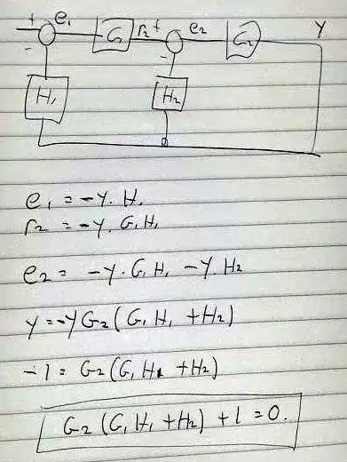
However, we have to watch the stability properties of the circuit. For this purpose, it is common practice to investigate the loop gain (determination of stability margins). To generalize the problem, we further should discuss the corresponding block representation (\$G_1,G_2,H_1,H_2\$) as shown under the circuit diagram. enter image description here

In this context, the following problem exists: We can identify three different feedback loops in accordance with three different openings:

  1. at output \$H_1\$ (\$G_2-H_2\$ closed),
  2. at output \$H_2\$ (\$G_1G_2-H_1\$ closed), or
  3. at output \$G_2\$ (all open).

And now the following questions arise:

  • From the beginning, is it possible to decide which of the three loops must be analyzed to find the relevant loop gain (resp. the relevant stability margin)?
  • With other words: Is there a dominant loop that mostly determines the closed-loop behaviour?
  • If the answer is "yes" - which loop, and why? (An answer to this question is important because we like to know where to introduce compensating elements, if necessary).

According to my knowledge, this question has not yet been answered in the literature.

EDIT/UPDATE: Because input/output nodes are not relevant for the loop gain(s) I have redrawn the system without these terminals. Now, we cannot discriminate between "inner" and "outer loops.

enter image description here

UPDATE (Okt. 2018):

Finally, I have a simple answer to the problem:

  • A system with two or more feedback loops has no "stability margin". Such a margin can be assigned to a each of the feedback loops only;

  • Hence, if we can define three different loops within the system, we can find three different loop gains and, therefore, three different stability margins (phase or gain margin);

  • The phase (gain) margin is a measure for the (unwanted) additional phase shift (or gain) that must be introduced into the loop to reach the stability limit.

  • Therefore, we cannot say, in general, that a loop with a phase margin of PM=30 deg is more critical that another loop in the same system having PM=45 deg. because the probability is important with which such a disturbance within a loop can occur. (Example: Time delay within a loop can produce severe phase lags).

LvW
  • 24,857
  • 2
  • 23
  • 52
  • You can use Mason's gain formula to deal with multiple loops: http://en.wikipedia.org/wiki/Mason%27s_gain_formula – Roger C. Dec 01 '14 at 15:25
  • Roger-I do not need the input-output transfer function (I spoke about LOOP GAIN). – LvW Dec 01 '14 at 15:28
  • @LvW: Really a good question. And i saw your answer to a similar question on edaboard, in 2009 :). – diverger Dec 01 '14 at 15:30
  • I think that the "equivalent loop gain" can be found in the denominator of the transfer function. If the denominator takes the form 1-F(s) then the loop gain is F(s). This article might help you http://www.circuitsage.com/images/blogs/lg_embedded_Jan09.pdf – Roger C. Dec 01 '14 at 15:41
  • Roger-thank you for the link; this paper is new to me. I will go through it soon. – LvW Dec 01 '14 at 15:46
  • Given left/right circles are input/output. Then H2.G2 is an inner loop and G1.H1.G2/(1+G2.H2) is the outer loop. Both loops need to be stable. Is there something I missed? – akellyirl Dec 01 '14 at 16:23
  • I've never done a composite amp. (Well I tried one, but didn't like it.) The only piece of advice I've heard is the second stage should be faster than the first. I assume you've read this, http://cds.linear.com/docs/en/application-note/an21f.pdf – George Herold Dec 01 '14 at 16:30
  • Perhaps I have made it not clear: The composite amplifier is an example only. The question concerns a general multi-loop case. – LvW Dec 01 '14 at 17:07
  • Roger.C, I roughly went through the paper (your ref) and - yes - it concerns my question, however, it is my (first) impression that it does not give a clear answer with justification. – LvW Dec 01 '14 at 17:14
  • LvW, I took a look in the paper too. And indeed it is a harder question than I thought at first glance. The paper seems to state that the "good" loop gain function will include all the poles of the system; so that stability analysis can be performed on this single function. But I'm quite rusty on control theory. I'll be watching the answers here :-). – Roger C. Dec 01 '14 at 17:53
  • "this question has not yet been answered in the literature." Of course it has. The problem is finding copies of such literature that are understandable. :/ – endolith Jul 29 '15 at 15:04
  • "Of course, it has"??? This sounds as if you are sure about it. Please, can you give any reference? Thank you. – LvW Jul 29 '15 at 15:45

2 Answers2

3

The diagram can be rearranged so that \$H_2G_2\$ is an inner loop and $$\frac{G_1H_1G_2}{1+G_2H_2}$$ is the outer loop.

It is required for the outer loop to be stable. The inner loop may be unstable with the full loop being stabilised by controller \$G_1\$. This is generally only done when absolutely necessary to stabilise an unstable plant.

Practically speaking, both loops should be required to be stable in a system such as this with standard op-amps.

As a rule of thumb for design simplicity, the \$G_2H_2\$ loop is designed to be stable with significantly higher bandwidth than the final loop bandwidth so that its phase delay can be neglected in the design of the outer loop; i.e. its phase/magnitude contribution to the overall loop is negligible at crossover.

enter image description here

To the OP's Update: The point of which loop to analyse: A straightforward analysis of the OP's loop (also the Updated equivalent arrangement) shows the stability analysis to be: $$G_2(G_1H_1+H_2)+1=0$$

for the rearranged circuit with the inner loop we get: $$\frac{G_1G_2H_1}{1+G_2H_2}+1=0$$

Applying simple algebra we see that it's the same result, as expected: $$G_2(G_1H_1+H_2)+1=0$$

Therefore you can analyse the loop several ways and get the same result. Considering the loop to consist of an inner and outer loop, is however, very convenient.

UPDATE: Here's the analytic justification for the loop stability equation to be $$G_2(G_1H_1+H_2)+1=0$$ Apologies for quality. I hope to enter as native format when I get time:

enter image description here

Null
  • 7,448
  • 17
  • 36
  • 48
akellyirl
  • 4,117
  • 1
  • 16
  • 30
  • akellyirl-yes, of course, the loop G2H2 could be considered as an "inner loop" (to be seen from the original drawing also). However, we have another alternative WITHOUT an "inner" loop: Multiply H1 with G1 and feedback to the same summing junction as H2(in parallel to H2). Now - which loop to open? Why? – LvW Dec 01 '14 at 17:04
  • akellyirl- I believe, your last two sentences are important (that`s my "feeling" also): The slowest loop is dominant (quicker loops with wider BW remain closed). – LvW Dec 01 '14 at 17:33
  • akellyirl, see my update: Where is an "inner" loop? – LvW Dec 01 '14 at 18:06
  • @LvW I've update my answer to try to illustrate why you don't need to assume an inner loop but still get the same answer. I can try to add a full loop derivation to illustrate later on. – akellyirl Dec 01 '14 at 18:10
  • akellyirl, I am afraid, with the update you missed the point. Both expressions are the denominator of the closed-loop transfer function (in two different forms). Thats correct. However, WITHOUT the "1" the rest gives you the loop gains which are DIFFERENT! – LvW Dec 01 '14 at 18:26
  • @LvW the expressions are not the denominator of the closed-loop transfer function, they are of the form L+1=0 where L is the loop gain. When L+1=0 then the loop has a gain of 0dB and 180 degrees phase shift, which is the stability criterion for a negative feedback system. Therefore the loop gains are equivalent. Which is exactly the point of your question as I understand it. – akellyirl Dec 01 '14 at 19:33
  • akellyirl, it is a simple exercise to show that the expression N(s)=G2(G1.H1+H2)+1 is the denominator of the closed-loop TF. And - exactly this is the reason that N(s)=0 is the characteristic equation with a solution that gives the poles of the TF. Please, check it again. You will see, there are three different loop gain expressions . – LvW Dec 01 '14 at 22:02
  • @LvW Please see my written loop equations from your block diagram. They are loop equations, quite definitively. I would be interested in seeing your assertion derived from first principles. – akellyirl Dec 01 '14 at 22:38
  • Based on your diagram (rearranged) and setting A=G´G1 (G´as defined by you) the closed-loop transfer function is A/(1+AH1). Insert your expression for G´ and multiply numerator and denominator with (1+G2H2). Then you have a denominator as given in your text. – LvW Dec 02 '14 at 08:15
  • Could you explain this mathematically? `As a rule of thumb for design simplicity, the G2H2G2H2 loop is designed to be stable with significantly higher bandwidth than the final loop bandwidth so that its phase delay can be neglected in the design of the outer loop; i.e. its phase/magnitude contribution to the overall loop is negligible at crossover.` – emnha Jun 10 '21 at 00:26
1

Rob Fox has done an analysis of a two loop system.

http://www.fox.ece.ufl.edu/Multiple-Loop_Feedback.html

He states (based on Bode and Mason) that the total loop gain T is $$(1+T) = (1+T_1)*(1+T_2^1)*...*(1+T_n^{1,..,n-1})$$

where $$T_n^{1,2,...,n-1}$$ means the loop n and all loop with smaller index are open. The order in which the loops are opened does not matter.

From this it seems that all loops are important.

For a given circuit one could calculate all combinations and search for the dominant loops.

The last two sentences are speculation. I try to learn this stuff.

JosefC
  • 256
  • 1
  • 5