2

I'm having a little trouble running my final bachelor experiment. My group and I are to find out what exactly causes extreme high frictional forces when pulling a steel cable through wet sand by varying the height of the sand above the cable.

We are, unfortunately, having problems with our motor. In labview we are using a ramp function to increase the voltage on the power supply over time. Usually from 0.4V to 4V in 400s where the sample rate of the entire system is 10ms. However we have noticed that when the frictional forces get too high, the motor starts acting up as shown in the graph below.

force vs time and current vs time

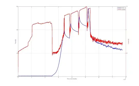
What you can see here is that as the voltage increases linearly (not shown) the current follows as well. We are measuring the force by placing a loadcell between the cable and the motor. As soon as the motor starts moving, the current drops and the motor starts pulling on the cable. The force starts increasing. But at some point the motor stops moving and the current shoots up. The decreasing force could be the tension being released from the pulley, the rope attached to the cable etc.

The stopping of the motor, however, could be caused by the fact that the frictional forces of the steel cable are too high (stick-slip). This is our problem. We don't want the motor to stop moving.

I was thinking of using a control loop to increase the speed at which the voltage increases, but I have no way of telling what the speed of the motor is. The tachometers we have won't work because the motor turns too slow. We only measure force, current and voltage.

EDIT: These are the motor specs: http://www.compucanjes.com/manuales/rs-555sh20.pdf

And this is how our (crappy) test setup looks test setup

Ortix92
  • 147
  • 6
  • Is the motor turning 1/3 or 1/5 of a revolution for each of those peaks? If so you are seeing the individual poles, and the fact that the force exerted by the motor is a function of its rotational angle due to its internal construction. I think you need a geared motor (say 100:1) as the simplest way to get relatively constant torque. –  Nov 29 '14 at 10:49
  • @BrianDrummond Forgot to mention that it is in fact a geared motor with a very high ratio (which I don't know at the moment). – Ortix92 Nov 29 '14 at 11:34
  • Then be aware that current demand by the motor is a pretty good measure of torque exerted by the motor. This may point to a mechanical issue. For example, is the cable acting as a spring? Thus the high current shows the motor winding up the spring again (the motor may be turning but the other end, at the load cell, is not) Alternatively if you want to torque control the motor, drive it from constant current, not constant voltage (i.e. ramp up the current) –  Nov 29 '14 at 11:40
  • We're unsure what the exact mechanics are under ground. But the steel cable does not stretch under these forces. It moves through the sand and builds up frictional force as it moves. We believe, that at a certain point the frictional forces are too high for the motor to handle until it builds up enough voltage. Driving the current is indeed an option we looked at but weren't able to execute it in time (we encountered the problem too late on friday) – Ortix92 Nov 29 '14 at 11:48
  • Check if the gearbox is binding as side force is applied to it. An outboard bearing (left of pulley in photo) would probably resolve that. That would account for increasing motor torque while "force" on load cell is reducing. –  Nov 29 '14 at 12:11
  • I suggest that if you're using a DC to control the motor it probably can't supply enough current to get the job done. – Scott Seidman Nov 29 '14 at 15:32

2 Answers2

2

Because friction does not vary linear with speed in this system, you are going to have a tough time getting a consistent speed with an open-loop system.

To a first order approximation, motor torque is proportional to current, and motor speed is proportional to voltage. In fact, in an ideal motor which has no winding resistance and is driven by an ideal voltage source, this is exactly true. So, you might try selecting a motor with a low winding resistance, and assuring that your motor driver is as low impedance as possible. This will give you better speed regulation in an open-loop system.

It will probably also help to select a motor with a high quality transmission with low backlash. Any slop in the transmission is really going to make things hard. Perhaps a high quality ball screw will give you a more linear and predictable transmission.

Another mechanical solution would be a flywheel, which if massive enough, would smooth out the torque variations from the slip-stick action to a manageable level.

However, if you really need a predictable speed, I bet you are going to need a closed loop system. You have a couple options here. A tachometer as you mention would be great, but probably you'd want it to be on the motor shaft, before the mechanical reduction. Here it becomes all the more important to have a good transmission, otherwise all the transmission slop will show up as error in your measurements, even if the motor speed regulation is perfect.

A somewhat less ideal solution is to measure the back-EMF of the motor. You may not get the same precision and responsiveness as with a tachometer, but it doesn't require any additional parts. See How can I measure back-EMF to infer the speed of a DC motor?

A final approach you may consider is using a stepper motor. Provided you can select a motor and transmission with enough maximum torque that steps aren't missed, then you can get a consistent speed in an open-loop system. An issue here may be the high torque ripple of such motors, which might be a problem for your experiment.

Phil Frost
  • 56,804
  • 17
  • 141
  • 262
0

The basic problem seems to be mechanical, not electrical. Your motor doesn't have enough power at low speed to perform the task you want it. Put simply, you are using the wrong motor.

To fix this, get a more powerful motor. If you don't need much speed from the motor, gear it down. Even the motor you have now can drag the cable smoothly at low speed with some gearing in there. You want the gearing so that the cable is moved at the maximum speed you want to test at when the motor is running a bit below its maximum intended speed. Perhaps your current motor can actually do this with the right gearing between it and the load.

Olin Lathrop
  • 310,974
  • 36
  • 428
  • 915