30

I am a physics teacher who did engineering and hated all things electrical! Hence when my students sometimes ask me how a voltmeter can measure the potential difference between two points if there is no current passing through the voltmeter. I can only assume that it is because having an infinite resistance is impossible, but I have never had the confidence to answer this without worrying about feeding them incorrect information.

My idea as it stands is that the resistance of a voltmeter is only theoretically infinite, in which case there will be a current flowing, however small, that can be used somehow by the voltmeter of a predetermined resistance to calculate the actual potential difference.

Can somebody explain whether I am along the right lines with this and help me explain this in definite terms or at least disabuse me of my assumptions and tell me the correct idea?

Peter Mortensen
  • 1,676
  • 3
  • 17
  • 23
  • 3
    I think this is a really good question - it bottoms out to yes, there will be some current flowing due to imperfect input circuits but these currents can be unrelated to the the input (i.e. leakage currents) so ignoring these, what mechanism does a voltmeter employ that just relies on measuring voltage rather than some side effect like current. – Andy aka Nov 27 '14 at 23:37
  • 2
    Shame on you, a physics teacher. :^) (Only kidding.) As other said real voltmeters draw current and real ammeters have some voltage drop. – George Herold Nov 28 '14 at 00:53
  • 3
    How can a [load cell](http://en.wikipedia.org/wiki/Load_cell) measure force if it isn't (significantly) squishy? Can you measure how hard you are pressing on a brick wall, even though the brick wall is immovable? – Phil Frost Nov 28 '14 at 17:46
  • @PhilFrost A force balancing device can have insignificant motion (statically, anyway), since the control system can have arbitrarily high gain. In reality the motion could be down 6 or more significant digits as in high-end ITAR-controlled acclerometers. – Spehro Pefhany Nov 28 '14 at 17:50
  • When we talk about a voltmeter having infinite resistance we usually do not mean a real voltmeter but an **ideal voltmeter**. It is the simplest model of a voltmeter because it does not affect the circuit being measured. --- As others wrote voltmeters usually do not have an infinite resistance. There are voltmeters which have (almost) infinite resistance but they do not have infinite reactance. – pabouk - Ukraine stay strong Nov 29 '14 at 00:07
  • In the crazies of electronics worlds, the fact that voltmeters are NOT ideal is a big deal. You can actually change the behavior of your circuit by putting the leads on. RF stuff is like this. In fact, you don't even need the voltmeter turned on. There are some highly tuned circuits which stop working when you touch the probe to them... the mere presence of the metal creates an antenna and prevents the circuit from working! – Cort Ammon Nov 29 '14 at 05:34

10 Answers10

24

The underlying difficulty seems to be the belief that some current must flow to measure voltage. This is false. Since you are a physics teacher, I'll explain by making analogies to other physical systems.

Say we have two sealed vessels, each filled with some fluid. We want to measure the pressure difference between them. Like voltage, relative pressure is a difference in potentials.

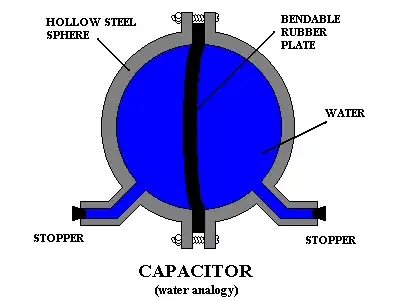
We could connect them with a tube which is blocked in its middle by a rubber diaphragm. Some fluid will move initially, but only until the diaphragm stretches to balance the forces of the fluids acting on it. We can then infer the pressure difference from the deflection of the diaphragm.

This meets the definition of infinite resistance in the electrical analogy, since once this system has reached equilibrium, no current flows (neglecting diffusion through the diaphragm, which can be made arbitrarily small and isn't necessary for the operation of the device).

However, it does not qualify as infinite impedance, because it has non-zero capacitance. In fact, this device is exactly Bill Beaty's favorite mental model of a capacitor:

capacitor (water analogy)

There are, in fact, devices that measure voltage that work analogously. Most electroscopes fall into this category. For example, the pith ball electroscope:

pith ball electroscope

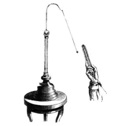
Many of these devices are very old and require very high voltages to work. However, modern MOSFETs are essentially the same thing at a microscopic scale in that their input looks like a capacitor. Instead of deflecting a ball, the voltage modulates the conductivity of a semiconductor:

MOSFET structure

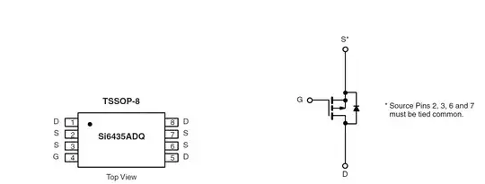
The MOSFET works by altering the conductivity of a channel between the source (S) and drain (D) as a function of the voltage between the gate (G) and the bulk (B). The gate is separated from the rest of the transistor usually by a thin layer of silicon dioxide (white in picture above), a very good insulator, and like the diaphragm device before, whatever very small leakage there is isn't relevant to the operation of the device. We can then measure the conductivity of the channel, and the current flowing in this channel can be supplied by a separate battery and not the device under test. Thus, we can measure a voltage with an extremely high (theoretically infinite) input resistance.

schematic

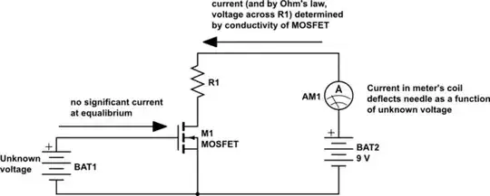
simulate this circuit – Schematic created using CircuitLab

QuantumRipple
  • 198
  • 1
  • 7
Phil Frost
  • 56,804
  • 17
  • 141
  • 262
  • As an interesting thought experiment, imagine a device with two movable metal plates and a motor/force gauge which repeatedly brings them closer and further apart. Such a device would seem to draw an AC current, even though no electrons would ever actually pass from one plate to the other or go through it in any manner. If attached to a "rigid" voltage source, one could measure the voltage by measuring the force required to move the plates; if not attached to a rigid voltage source, the motion of the plates could change the voltage on them. – supercat Nov 29 '14 at 01:29
  • Thank you very much for this answer. The rubber diaphragm idea will really help them to visualise what is going on as they are much better with "physical" concepts like pressure. Hopefully it will also give them a bit of an idea into capacitance and impedance ready for their studies next year. Thank you also for bringing back dusty memories of transistor theory from lectures at university. Seems I didn't hate electrical engineering as much as I remember! – William Tabary-Peterssen Nov 29 '14 at 10:31
  • Re "Bill Beaty's favorite mental model of a capacitor", do you know if that model correctly models the ½(CV²) energy-storage characteristic of a capacitor? – James Waldby - jwpat7 Nov 29 '14 at 20:58
  • @jwpat7 to the extent that the rubber obeys [Hooke's law](http://en.wikipedia.org/wiki/Hooke%27s_law), I think it would. This is probably only [approximately true for real rubber materials](http://www.wired.com/2012/08/do-rubber-bands-act-like-springs/). The analogy to Hooke's law for capacitors is \$V=Q/C\$, that is, the work required to put another unit of charge through the capacitor is linearly proportional to the charge put in it so far. – Phil Frost Nov 29 '14 at 22:17
  • 1
    Perhaps I'm missing something but in your example dc current has to flow to bias the FET. Or was your first paragraph just rhetorical? Or can we really derive a way to *measure* voltage without electron flow? – user6972 Nov 30 '14 at 21:06
  • @user6972 MOSFETs don't require a DC bias current, except for a very, very tiny current that must exist only because perfect insulators don't exist. This is why CMOS is the topology of choice for CPUs, what enables flash storage, and why MOSFETs are so sensitive to ESD. To prove it to yourself, light an LED through a MOSFET on a breadboard, then disconnect the wire connecting the gate to Vcc. The LED will stay on for quite a long time because the gate capacitance remains charged enough to keep the MOSFET on. – Phil Frost Nov 30 '14 at 23:02
  • @PhilFrost I know this is why I don't understand your first paragraph. See Gary Scarr's answer. – user6972 Dec 01 '14 at 22:02
  • @user6972 The question asks about infinite *resistance*, not infinite *impedance*. This means some current *can* flow, temporarily. Did you try reading past the first paragraph? – Phil Frost Dec 01 '14 at 22:39
  • 1
    @PhilFrost There's no difference because you can't temporarily measure something without reducing the charge and thus introducing some finite resistance. – user6972 Dec 04 '14 at 22:13
  • @user6972 I say more than once in this answer that some current will flow *transiently*. That's not *resistance*, it's *capacitance*. It's explained at length, past the first paragraph. I'm sorry, but I can't tell if you are disputing that, or if you just haven't read past the first paragraph, or you have some other issue or what. I don't know what "temporarily measure" means, either. – Phil Frost Dec 05 '14 at 00:52
  • @PhilFrost When you make the measurement you're dissipating power from the circuit because it is not returned and it does not remain part of the system. The electrical analogy to the circuit is a transient resistive load. – user6972 Dec 08 '14 at 02:27
  • @user6972 Did I assert somewhere that the device I described requires zero energy from the device under test? – Phil Frost Dec 08 '14 at 13:35
  • @PhilFrost Then the electrical model the circuit "sees" would have to include resistance. Even if you connect a capacitor and then remove it there is still a resistive function involved due to the ESR caused by energy loss. In addition as discussed there is no non-resistive probe. (I am only pointing all this out because a physicist asked this question.) – user6972 Dec 11 '14 at 17:54
  • @user6972 Can you tell me what *specifically* in the answer is bothering you? Which words in particular are wrong, incomplete, or misleading? – Phil Frost Dec 11 '14 at 18:57
  • @PhilFrost Briefly. The first 2 sentences. The water capacitor analogy assumes measurement after steady state (when water is done flowing), but it's not a correct model for insertion and removal of a meter. Pith ball electroscope also loads down the fields in the same way a capacitor or inductor would -- causing current to flow. The other solid state examples also require current flow as discussed. – user6972 Dec 16 '14 at 21:19
17

It's relatively easy to make a voltmeter that will have a typical input current of a few fA at room temperature. That's still tens of thousands of electrons per second.

You could make a voltmeter (in theory anyway) that would draw zero steady-state current from the source by (say) balancing electrostatic forces across a gap with magnetic or mechanical force. If the insulators didn't leak and the device was in a vacuum, there is no mechanism for current flow beyond what it takes to equalize the potential on the measuring leaf with the unknown voltage.

A MOSFET works almost like the mechanism described above in that there is no inherent flow of electrons (to or from the gate) that is required to make it work once the gate is charged to the input voltage. Any gate leakage is a function of imperfections and of auxiliary structures such as ESD protection networks. A small and unprotected "floating gate" memory cell might leak one electron per day, which is pretty close to being perfect. If such a gate could be connected to your source without compromising the leakage (or rupturing the thin gate oxide with too much voltage) it would be almost perfect, except for that tiny leakage and the charge of the gate capacitance.

Spehro Pefhany
  • 376,485
  • 21
  • 320
  • 842
  • 10
    A "gold leaf electroscope" is exactly such a voltmeter : its input resistance can indeed be infinite without affecting its operation (it does have a small capacitance, so it accepts a small charge as it operates) –  Nov 28 '14 at 12:15
  • @Brian Drummond: if the [_gold leaf electroscope_](http://www.gcsescience.com/pse4-electrostatic-gold-leaf-electroscope.htm) is a voltmeter, then where is its second input? I was on the impression that the GLE is measuring some absolute potential on its single input, rather than difference of potential as the voltmeter (or MOSFET) does. – fgrieu Nov 30 '14 at 18:08
  • 1
    @fgrieu one input is the electrode on the electroscope, and the other input is the object near it. These two objects make a capacitor, and the electroscope measures the difference in potential across this capacitor. – Phil Frost Dec 01 '14 at 13:20
8

A theoretical voltmeter, as you would find in a circuit simulation program, will have infinite resistance, but any real voltmeter will have a finite resistance, and will therefore allow some current to flow.

My DVM has an input impedance of > 1 GOhm on the 400 mV AC or DC range, and 10 MegOhm on other ranges.

Peter Bennett
  • 57,014
  • 1
  • 48
  • 127
  • Yep, and just to add to this answer, you can actually see the loading effect of this non-ideal resistance by trying to measure the voltage across a rather high resistive load. In such a case, you will get inaccurate voltage readings due to the internal resistance being so close to the measuring resistance. – Jarrod Christman Nov 28 '14 at 13:22
  • In fact, often (analogue) multimeters will have the resistance indicated somewhere on the front, with the intention that when you know you are working with high resistances, and require high accuracy, you can calculate the correction required. – peterG Nov 28 '14 at 17:41
8

Nobody seems to have answered the fundamental question of how a theoretically perfect voltmeter would work. It can't. You eventually get down to quantum mechanics and Heisenberg's Law that you can't measure anything without affecting it to some degree. In voltmeters you've got to get some charge to pass to build up the balancing potential that you are using to move your indicating device. Of course, as Spehro has pointed out, all practical voltmeters are far far from the Heisenberg limit.

rdtsc
  • 15,913
  • 4
  • 30
  • 67
Gary Scarr
  • 81
  • 1
7

I think that, in order to answer this question, a pedagogic way would be to ask them why do they think that the infinite resistance is a problem in order to measure voltage.

There is no fundamental need for a current to flow in order to measure a voltage... I think the discussion would be interesting for them to understand electricity and sensors in general.

The voltmeter must have a high internal resistance so it doesn't interfere with the circuit. I think you can also talk about ampere-meters : if they are connected in series they must have a low resistance, but there are some ampere meters that do not need to be part of the electrical circuit (based on Rogowski coils for instance).

edit : Maybe you could also use some analogy with pressure/water flow.

TZDZ
  • 171
  • 2
  • I agree that there are some very useful concepts that could be teased out of the questions you mention at the top of your post. I will use it to see if it engenders any independent research on his part. Who knows, he may even end up reading this post! Again many thanks for your pedagogic proposals. – William Tabary-Peterssen Nov 29 '14 at 10:35
6

There are electrostatic voltmeters that indeed have a "current" of zero. Basically, they work by having the electrostatic force move an almost balanced indicator needle from its point of equilibrium.

Now while those voltmeters do not take a nonzero permanent current, of course the charge must still create a field in order to cause an effect and thus is stored in the voltmeter which acts as a capacitor rather than a resistor. And if the needle works against air resistance, the charges leave at a lower voltage on average than when they entered the voltmeter, so there is work done in spite of no net current being consumed after the voltage drops to zero again.

user59239
  • 61
  • 1
  • The idea of work being done and thus energy being transferred is an excellent way for them to appreciate the relation between potential difference and charge. I am assuming that there will be some energy transferred to whatever the needle is balanced by, in terms of a minute amoung of the EPE in the material causing the balancing force being dissipated as heat? Would there be any other (macro) scale losses that you can think of – William Tabary-Peterssen Nov 29 '14 at 10:40
3

Differential voltmeters theoretically have infinite input resistance when they are nulled. They measure voltage by adjusting an internal voltage source to match the input voltage as indicated by a zero reading on a meter. In practice, the input resistance is limited by leakage effects but, again in theory, no current is drawn from the measured voltage.

Barry
  • 15,733
  • 1
  • 26
  • 28
  • Current will flow while you are adjusting the internal voltage source. This could have an irreversible impact on the measured circuit. – Kitana Nov 30 '14 at 01:16
2

You're right about the difference between a theoretical infinite input resistance and a practical voltmeter. A good voltmeter might have an input resistance of the order of tens of megohms, at least, but it's not infinite. A tiny current will flow, and the input amplifier in the voltmeter will use that to make the measurement.

Of course, an old-style moving-coil meter will draw a current of perhaps 50uA, or as much as 1mA in the case of a really cheaply-made meter.

John Honniball
  • 2,799
  • 11
  • 10
2

Since infinity is a theoretical concept, we can use calculus-style reasoning to explain it. As the meter's resistance approaches infinity, the current through it approaches zero. Although we never quite get there, we get "close enough" to believe it.

It's also worth mentioning, that there may be another kind of voltmeter that doesn't draw current. In static electricity experiments we observe two charged objects repelling each other. They push apart just from the force of the charges, and don't consume any current. So, one might construct a voltmeter from that--at least, theoretically.

gbarry
  • 8,615
  • 21
  • 31
1

Your explanation and idea are "right on." "Real" (as opposed to theoretical) voltmeters, do draw some current to generate a "reading." By using amplifiers (and/or other methods), one can approach the theoretical limit of infinite input impedance, but never reach it. So all you have to explain to your students is that they are right, it would be impossible to obtain a perfect measurement, without affecting the thing being measured. However, if we can accept a less than perfect measurement, then it is doable.

Guill
  • 2,430
  • 10
  • 6