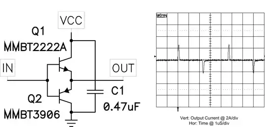
This gate driver circuit will allow much faster switching speed.
From this discussion. Note that Q cam be a bipolar transistor with pros and cons. Probably remove R4, drive with1k from PIC and place say 10k base t ground. Add a small cap (maybe 1 NF or less, across series 1k drive resistor as a "speedup" cap. This helps with charge traaansfer into/out of base and improves switching time. Note that Q2 and Q3 are emitter followers with polarity accordingly. FET gate swing will be 1+ Vbe drop away from each rail - this susually matters only when drive is low voltage. In this case PIC swing is 3V3 but main FET gate swing is ~= 12V so loss of 2 x Vbe is unimportant.
3V drive from PIC needs a FET at Q1 with a low Vgsth and 2N7000 shown in circuit may be marginal. Use of a bipolar for Q1 makes lower drive voltages OK.
I have used this cct with good success in several hundred thousand products with a bipolar at Q1, driven by a MC34063 low cost SMPS IC running at as low as 3V, with R1 as a pull down as IC is open collector. Main FET needs Vgsth of about 1V in that case. (Used in these - larger ones, not smaller ohnes).
If you do not need to level shift you can use just the driver pair.
The circuit below and a number of other good ideas can be seen here Discrete devices—a good alternative to integrated MOSFET drivers - one of a series of EE Times "Power Tips".
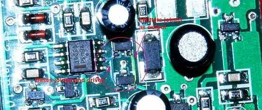
Slightly larger
Re original schematic - since improved:
Avoid all angled lines - make lines vertical or horizontal
Place input at left lower
Place ground reference/symbol at bottom.
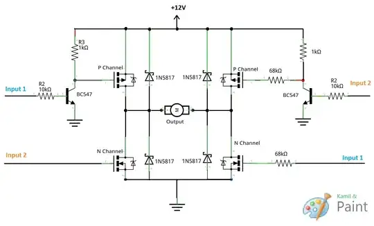
Circuit function notes:
Reason for using 68k's in RHS and not left is not clear BUT gate switching times with 68k will make rice pudding look fast.
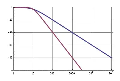
Gate capacitance typically around 1 NF. Work out how long to charge & discharg gate caps. This must be short compared to shortest on time to keep losses low.
1k is OKish for very low speed PWM but for real speed you want gate drivers.
These can be 2 jellbean bipolars per gate.
Your gates pull to full V+ when off.
This is OK at 12V supply for most FETS (not all) but as voltage goes up Vgs_max will be exceeded. So, clamp g-s with reverse vbiased zeners with Vz > Vdrive max and < Vgsmax. –
Related:
Superb superb - Index to power tips series
http://m.eet.com/media/1120488/powertipserieslist.pdf