4

enter image description here

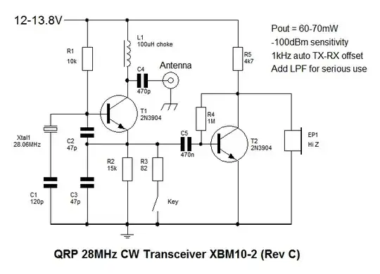
In a circuit like this, can the crystal oscillator be replaced with a DDS such as a AD9850? If so can it just be dropped in or would other components have to be changed?

Second question, how sensitive are simple transceivers like this to slight changes in capacitance, for example, a 110pf capacitor instead of the 120pf one below the crystal?

Final question, if I want to change the DDS frequency(to 14Mhz for example) do all the capacitors, etc need to be changed?

Thanks so much for your time.

user701329
  • 53
  • 2
  • 5
  • How are we supposed to know if it can just be dropped in, when we don't know what it's going in? – Matt Young Nov 20 '14 at 21:34
  • @MattYoung - this appears to be the *entire* transceiver. – Chris Stratton Nov 20 '14 at 21:43
  • 1
    As for the question itself, **no**, as the DDS chip output will require **a lot** of cleanup before you put it on an antenna. You will also need to change the programming between TX and RX, since you can't "pull" a DDS off frequency by loading it to generate an audible sidetone the way you can a crystal. – Chris Stratton Nov 20 '14 at 21:44
  • @ChrisStratton This is the entire transmitter, my friend built it and it actually works really well considering. I should have clarified that if I did this I would use a board that has the AD9850 and filtering built in,[this](http://i.imgur.com/0bHAvMd.jpg) is an oscilloscope of a 10MHz signal directly from said board. Is that "clean?" And thanks so much for your help! – user701329 Nov 20 '14 at 21:51
  • 1
    As any ham reference will tell you, an oscilloscope is not a sufficient instrument for measuring **spectral distortion** - you can't judge the presence or absence of overtone components from the shape of the waveform once they are substantially weaker than the fundamental. These aren't just a problem in emitted radiation - they also mean your receiver may spuriously receive out-of-band signals, which can be a problem as those may be much stronger than the ones you are intending to receive. Set your DDS to 1/3 of 28 MHz and see if you can receive its 3rd overtone. – Chris Stratton Nov 20 '14 at 21:56
  • @ChrisStratton I'm actually a general.... anybody can pass the test it seems. Thanks much, I'll do as you say and hopefully find some way to filter it. – user701329 Nov 20 '14 at 22:13

3 Answers3

5

No. In this case, it seems like the crystal is being used as a bandpass filter. The idea is that the gain of the amplifier will be the largest in the passband of the crystal. You cannot just replace it with a DDS as a DDS does not act like a filter, it acts like an oscillator. You might be able to get away with a DDS for the transmit function only, but it's not going to work for the receiver.

alex.forencich
  • 40,694
  • 1
  • 68
  • 109
0

My approach to solve this would be: -

Try simulating the above circuit (LTSpice or PSpice etc..) and then when happy it seems to work, inject a waveform (as if from the DDS) onto the base of T1 (xtal removed of course). Mess around with levels until you are satisfied it works across the range of frequencies you desire.

Andy aka
  • 434,556
  • 28
  • 351
  • 777
0

It would be tough to do the RX because it is actually a regenerative or self oscillating detector .This is why the simple circuit works well .The TX is easy .Why not take a reasonably simple direct conversion reciever and try the DDS as the LO.

Autistic
  • 14,235
  • 2
  • 27
  • 65