1

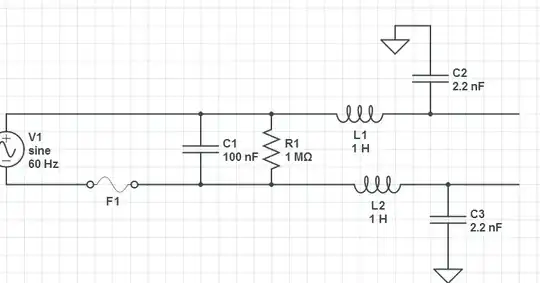
I'm designing a switching regulator for motor controlling, I have tried this circuit with spice but it does not work:

enter image description here

The problem is that the voltage on the load of the regulator never goes down, as is depicted in the picture:

enter image description here

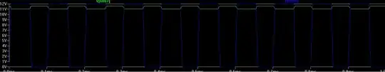
Is there anyone to explain me why?

Adam
  • 915
  • 1
  • 10
  • 26
Daniel
  • 149
  • 3
  • 11

1 Answers1

1

You are using a model of a P-channel FET, which is hooked upside down, so body diode conducts all the time. Source needs to connect to +12V and drain needs to connect to R1 C2 node. Also, D1 is in the wrong place, anode should go to ground while cathode goes to R1 C2 node.

Here is a related question concerning drive of brushed DC motors.

gsills
  • 7,133
  • 16
  • 22