12

Why does 555 timer IC has three 5k resistors and not other values, like 10k-10k-10k or something else?

555 timer (in astable mode)

Ricardo
  • 6,134
  • 19
  • 52
  • 85
  • 1
    It doesn't say "5k" anywhere in that diagram ... – pjc50 Nov 17 '14 at 13:29
  • 2
    it generally is 5k (that's why called 555 timer) – Sudhanshu 'Sid' Vishnoi Nov 17 '14 at 13:31
  • 1
    Didn't know that one. Apparently, R=5kOhms. Not the greatest references, but here are a few evidences: http://www.edaboard.com/thread83725.html, http://www.engineersgarage.com/tutorials/555-timer-ic-introduction-basics-working-different-operating-modes – Ricardo Nov 17 '14 at 13:36
  • 9
    [Not true.](http://www.semiconductormuseum.com/Transistors/LectureHall/Camenzind/Camenzind_Page2.htm) "How did the 555 name come about?" "Signetics had “500” numbers, and the earlier product I worked on was the 565, 566 and 567. It was just arbitrarily chosen. It was Art Fury (Marketing Manager) who thought the circuit was gonna sell big who picked the name “555”." – Ignacio Vazquez-Abrams Nov 17 '14 at 13:37
  • 1
    The mistery unfolds... but the OP question still holds, why is R usually 5k? – Ricardo Nov 17 '14 at 13:41
  • 4
    It usually isn't. The 5k value comes from the myth. I believe it's actually around 4.2k. – Ignacio Vazquez-Abrams Nov 17 '14 at 13:44
  • I imagine there was some basis for optimization that may or may not still apply, and that any speculation would just be an opinion-based guess. – Scott Seidman Nov 17 '14 at 13:54
  • 3
    I think this question should not be on hold. Asking why something is a particular value is important in understanding the designer's trade-offs. Whether it's 5K or 5.1K may be opinion-based, but the OP was asking about electronically significantly differences in values. – Spehro Pefhany Nov 17 '14 at 16:01
  • Signetics had a whole bunch of army surplus 5K resistors. – Hot Licks Nov 17 '14 at 18:46
  • 2
    Because if it was 6k, the product would've been the 666 and probably not sold nearly as well. – Dan Is Fiddling By Firelight Nov 17 '14 at 22:11

3 Answers3

18

The original 555 with 5K resistors: http://www.designinganalogchips.com/_count/designinganalogchips.pdf

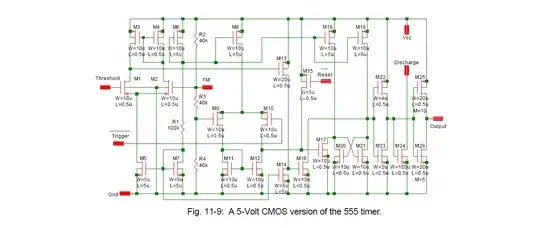
And here is a CMOS version with 40K resistors:

enter image description here

The choice of resistors for R7, R8, R9 (bipolar version) would be influenced by two things-

1) The desire to minimize power consumption (as high value as possible without using up too much chip area)

2) The desire to minimize temperature variations due to beta changes of Darlington pairs Q3/Q4 and Q12/Q13.

The second point does not apply to the CMOS version.

It's easy to see that the Thevenin equivalent source resistance for either node is 2/3 of the resistor value.

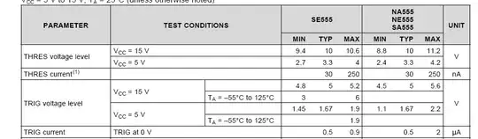
We can easily divine what the production limits are on the currents drawn at those nodes from a 555 datasheet- the circuit is symmetrical (horizontally) and the currents will be the same as the trigger and threshold currents. The currents are quite different, probably because of the low beta of the lateral PNPs.

Hans Camenzind says the comparator offset can be as large as 30mV, which implies a large offset voltage on top of the 7mV maximum due to the input bias current, but the input bias current is quite variable with temperature (maybe 3:1 over operating range). If we assume it changes from 0.7uA to 2uA, at 5V that would be a change in threshold of 0.25% or about 15ppm/K. Overall actual accuracy is about 24ppm/K, so the resistors are not overly dominant (the offset will change at something like proportional to absolute temperature).

Back in the 70's, 10mA at 15V or 3mA at 5V was considered reasonably low power, so HC probably chose the resistors as being "reasonable" -- not too big and not too small, and this was all pre-computers so he would not have had the option of running an optimization routine to get odd value that minimized some arbitrary cost function.

enter image description here

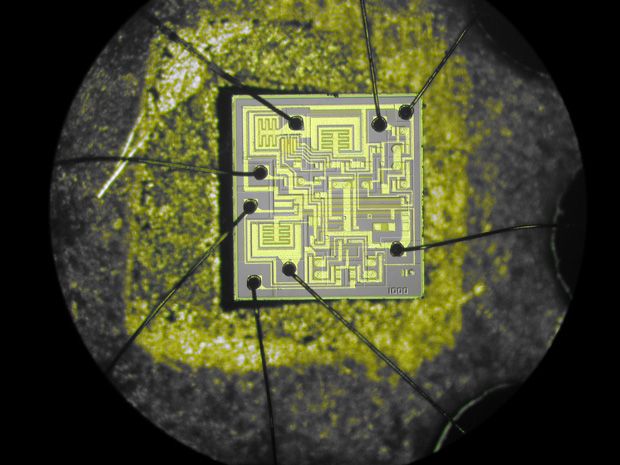
Here's the actual die photo (as taken by HC and published in IEEE Spectrum), with the resistors highlighted.

enter image description here

Spehro Pefhany
  • 376,485
  • 21
  • 320
  • 842
  • 1
    Nice picture! It's easy to work out that pin 1 is in the upper-right corner, and that they go counterclockwise from there. Pin 3 has two large transistors for its totem-pole output, and pin 7 has one large transistor for its pulldown. Pin 5 is indeed directly attached to the upper tap of the divider chain. – Dave Tweed Nov 17 '14 at 16:25
  • How a out input impedance? – Scott Seidman Nov 17 '14 at 18:01
  • @ScottSeidman As a design consideration? I imagine Hans would have wanted it as high as practical- later designs (including his own low-power bipolar one designed 33 years after the first) all had higher divider resistances- 20K to 40K at least. Since the absolute value of diffused resistors is not very well controlled (and it's completely unspecified except by what you can guess from the supply current), it should be driven with a relatively low-Z source anyhow. – Spehro Pefhany Nov 17 '14 at 18:12
9

It doesn't matter what the exact value is, as long as all three resistors have the same value.

The value is a tradeoff among various design constraints. On one hand, you want the value to be large, to minimize the quiescent current requirements of the chip. On the other hand, large-value resistors take up a lot of physical space on the chip. There is also the consideration that you want the input bias currents of the comparators to be a tiny fraction of the current in the resistors.

Taking all of this into account, the designer settled on a value of around 5K.

Dave Tweed
  • 168,369
  • 17
  • 228
  • 393
5

Let's look at the silicon!

The three 5k resistors are the horizontal bars at the top of the chip. Making resistors in silicon is a pain; the available materials are all fairly conductive, so it's hard to make large-value accurate resistors. At the time of design of the 555 the minimum feature size was quite large, large enough to be seen with an optical microscope as in that photo. There's the additional design constraint that those resistors affect the accuracy of the timer. That probably determines the choice of the material, which will have a certain resistance in ohms per micrometer.

From there, we can see that the 5k resistors could not be made much larger in the available space. Perhaps they could have been made 6k, but choosing 5k makes it simpler for the users of the chip to compute timer values by hand.

(I think the "5.0E" on the chip there is actually a registration mark indicating that that's layer 5, like the smaller ones at the top of the chip. Not a component value.)

pjc50
  • 46,540
  • 4
  • 64
  • 126
  • The actual value of the resistors has nothing to do with calculating timing values, which only depends on their ratios. In fact, that was one of the key insights of the 555 design. Also, that photo is of the CMOS version, which doesn't use 5K resistors anyway. – Dave Tweed Nov 17 '14 at 15:23
  • [Here's](http://www.usmicrowaves.com/miscics/555.jpg) an actual NE555 (clone) die photo. Maybe someone can make something of it. – Spehro Pefhany Nov 17 '14 at 15:44
  • [Here's](http://spectrum.ieee.org/img/05W25Chipsf1Signetics555-1375708907552.jpg) a much clearer photo (credit to the designer) – Spehro Pefhany Nov 17 '14 at 15:52
  • 1
    Interesting that they interleaved the resistors on the CMOS version, to better match the resistors against process and die temperature gradients. – Spehro Pefhany Nov 17 '14 at 16:40