0

I got a shift register which I use to PWM LEDs. Since I multiplex this toggling I noticed some "afterglowing" if the next LED is not active of the same color. (RGB cathode) Multiplexing by the MOSFET and PWMing by the PNP.

I already found out, that it is not the MOSFET which is too slow. So I tried increasing the toggling speed of the PNP but I was not sure how to do so. I thought of pulling it up, so I tried it with some high resistors around 1-5k but this does nothing. After this I used smaller till I used the 20Ohms and noticed that the glowing is extremely minimal now.

So my question is, how do I do this right? Sure it does work now but I'd like to understand how to increase the speed to some kind of maximum. Is there a better solution which I can do even after soldering the 510? I can't change the 510 Ohm and 120 Ohm in front of the PNP and MOSFET since I already soldered them but I can add a line to pull them all up for example.

Down here some example how it looks:

schematic

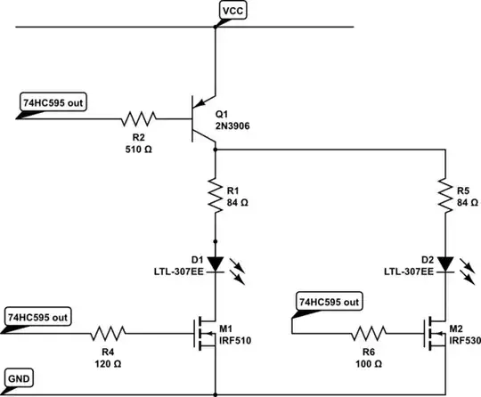
simulate this circuit – Schematic created using CircuitLab

BennX
  • 119
  • 7
  • 20 ohms on the output of the74HC595 renders it unusable. – Andy aka Nov 12 '14 at 13:03
  • But it works as it's drawn here. I know that the I should be to high i guess. ~25mA and the 74hc595 can handle 20mA. But if i use the next higher (47 Ohm) i still do have the gloweffect. – BennX Nov 12 '14 at 13:04
  • I can't tell you why you think it works - I can only advise you that you will be exceeding the ratings. – Andy aka Nov 12 '14 at 13:12
  • I don't think it works i tested it on a breadboard. I am sure that it wont be good for the register but thats why i ask if there is a other solution. I'll check if 30 Ohms works which would be in the ratings – BennX Nov 12 '14 at 13:14
  • 1
    Show a circuit that works (but with afterglow) then ask the question. At the moment you are confusing the issue with a "possible" solution that cannot work correctly. – Andy aka Nov 12 '14 at 13:17
  • 1
    updated the circuit. This seems to be to slow. If i reduce my multiplexing frequency it gets less afterglow. – BennX Nov 12 '14 at 13:20
  • 1
    I guess it's still not clear to me how the "next" LED interfaces with the circuit you have drawn. – Andy aka Nov 12 '14 at 13:34
  • ah give me second to add "a second one". Updated it. In this case if i set the first led on and the second off the second still "glows". (one time PNP 0 and PNP 1) – BennX Nov 12 '14 at 13:38

1 Answers1

4

Human eyes have a log response, so losing a bit of brightness is a lot less undesirable than some brightness where it doesn't belong.

The "right" way to do this, in my opinion, is to insert some dead time so that the drivers have a chance to settle out. IOW, turn off the one driver, wait and wait and wait (that's 3 microseconds perhaps) and then turn the (updated) drivers back on.

How fast are you multiplexing? Don't go excessively fast, there's no advantage. The 74HC595 is a push-pull output and it will suck the charge out of the base of the PNP pretty fast as it is. You could try ~100pF across R2 or (!) a Schottky clamp diode from the collector to base, but we're talking a visual display here, presumably, so that's a bit silly.

Edit: The 100pF is called a "speed-up" capacitor. It allows the 74HC595 p-MOS transistor to remove the base charge more quickly. Ideally it has a a value to give a rectangular waveform as shown below- 0.1uF is too large, you should need no more than a couple hundred pF. This page is well worth reading, and below image is taken from there. See also this answer.

enter image description here

You need one per transistor, same as the resistors. If it's SMT you could retrofit by putting a small cap literally on top of the resistors.

Spehro Pefhany
  • 376,485
  • 21
  • 320
  • 842
  • Yey you are right its for some visualisation. A 0,1uF did it! It has a slightly glow of all now but hard to see. Can i use one 0,1uF for 25 PNP resistoers or do all need "their" own? (got 75PNP and 5Mosfets in total to pwm 125 leds at the time) Could you shortly explain why this works i have a guess but i am not sure? – BennX Nov 12 '14 at 13:53
  • 1
    See edit please. – Spehro Pefhany Nov 12 '14 at 14:39
  • I already read about that but i think i didn't get that in my mind. I had some 0.1uF here so i tried it with that to see if it works as expected. Ill get a bunch 100pF and retrofit them as you said which should work without any problem. Thanks again. – BennX Nov 12 '14 at 14:49
  • One last question. Does the speed-up-cap also works for mosfet or is this useless since they have a cap inside...(I am sorry if this are some basic questions...) – BennX Nov 13 '14 at 14:49
  • 1
    Yes, it would work for a MOSFET. The "cap inside" is the combination of the gate capacitance and Miller (drain-to-gate) capacitance, and it is what you are fighting to get it to switch quickly. What would be more effective would be to parallel R4 with a diode (so it conducts when the MOSFET is turning off), and you could actually increase R4 to make it turn on **more** slowly and off more quickly. – Spehro Pefhany Nov 13 '14 at 15:47
  • well i need both. Quick on and off asap to have a clean animation of the RGB cube. So i guess ill put a 100pF also paralell to the R4. I just ordered enough to put them everywhere. Thanks again! – BennX Nov 13 '14 at 17:28
  • 1
    Humor me and try the slow on/fast off idea. – Spehro Pefhany Nov 13 '14 at 17:48
  • 1
    Well i am sure you are way better/you know way more about electronics than me so sure i trust you but i dont got diods by hand. Somehow i forgot to order them when i created my basket for the cube. Got hell alot of resistors and so on but no diods... Who could know that i need them. *laugh* What effect does it have if i slow down the "ON" of the mosfet? I dont get the reason not to "push the leds up" – BennX Nov 13 '14 at 17:53
  • 100pF seems to be to small. They still have "afterglow". With 0,1µF they don't. So i guess ill sprinkle 0,1µF in the circuit to have the desired result. – BennX Nov 15 '14 at 10:26