If you take the circuit below, with the switch closed, assuming the Tank circuit is tuned to resonate at the same frequency as the source, then I would expect the tank to become charged, and the impedance to skyrocket, such that the AC power supply simply drives the AC pump as usual. (The pump is just a solenoid shuttling back and forwards and some valves). If the switch is now opened, what happens? Would the energy stored in the tank discharge gradually as an AC current that could keep the pump working for a short time, as a capacitor might in a DC circuit? Or will it simply bounce around in the tank until it runs out of steam, or go through the pump once as a DC pulse and stop? (or anything else?).
-
What you're looking for is the Q of a parallel L-C-R circuit, where the AC pump is the parallel resistor. This determines how many cycles of AC you will see after disconnection. If you need the AC to decay to nothing over 1 second (50 cycles), take Q=50. Standard formulae, easy to find. This allows you to calculate L, then the C you need to resonate that L at 50Hz. TL/DR : you probably won't like the resulting numbers. – Nov 12 '14 at 11:57
-
@BrianDrummond The pump is an inductive device though, so you must take its inductance (in parallel with the L of the tank) into account, surely? – Majenko Nov 12 '14 at 12:01
-
1Any electric motor (properly loaded) is primarily a resistive load, with the inductance as a second order effect. You probably need to factor it in, but it's likely to be millihenries compared with the (gut feel) tens of henries or more he'll need for the tank. Much more problematic will be the resistance of that huge inductor... – Nov 12 '14 at 12:05
2 Answers
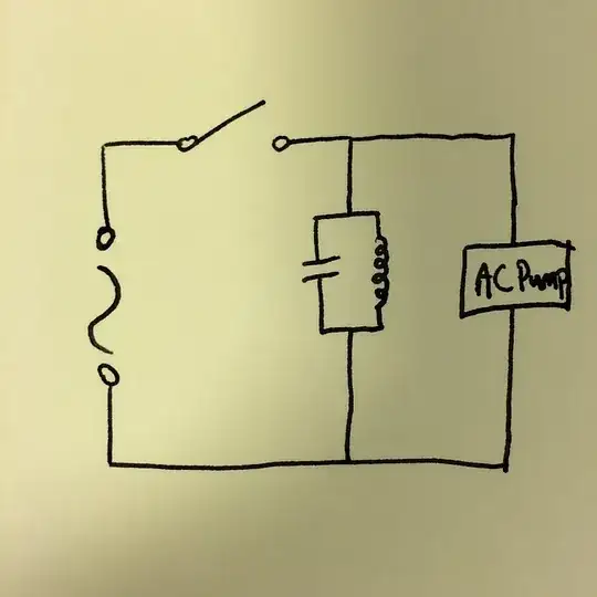
Yes, your analisys is correct and the tank does essentially store AC. With a theoretical ideal inductor and capacitor, the tank would continue producing the same AC voltage when the switch is opened and with no load connected. If a resistive load is connected, the AC voltage would decrease in amplitude exponentially, just like the DC voltage on a capacitor would when a resitive load is connected to it.
HOWEVER, back here in the real world, the inductor and capacitor required to store a meaningful amount of energy would be large and expensive. Also, real inductors in particular are far from ideal because of the resistance of the wire, and core losses (you can use air core, but then you need it to be even bigger).
Let's do a example to see how large and unrealistic the values get. Let's be generous and say we're only trying to power a 10 W load for a little while, so we want to store 100 J. Let's say the AC source is 120 V at 60 Hz, which is common line power here in North America. Twice per cycle, all the stored energy is either in the cap or in the inductor, so we can calculate the requirements of each independently. The energy in a capacitor is:
E = ½ C V²
where E is energy in Joules, C is capacitance in Farads, and V is EMF in volts. The 100 J will be stored in the capacitor at the peak of the voltage cycle, which is sqrt(2) times higher than the RMS, so 170 V. Solving for the capacitance:
C = 2 E / V² = 2(100 J)/(170 V)² = 6.92 mF
The resonant frequency of a L-C tank is:
F = 1 / 2π sqrt(LC)
where F is frequency in Hz and L is inductance in Henrys. Solving for the inductance:
L = 1 / (2πF)²C = 1 / (2π 60 Hz)²(6.92 mF) = 1.02 mH
The energy stored in a inductor is:
E = ½ I² L
where I is the current in Amps. Solving for the current:
I = sqrt(2 E / L) = sqrt(2(100 J)/(1.02 mH)) = 444 A
So, to store 100 J at 120 V and 60 Hz, the tank circuit requires a 7 mF 170 V capacitor and 1 mH 450 A inductor.
Real inductors have real equivalent series resistance. We want the tank to supply 10 W initially, so let's say we don't want the inductor dissipating more than 1 W of that on its own. The peak inductor current is 444 A, so the RMS current thru the inductor is 314 A. To dissipate only 1 W, the inductor's DC resistance needs to be only 10.2 µΩ. Yes, micro-Ohms.
To make things even tougher, the same current goes thru the capacitor, which also must have 10.2 µΩ ESR (effective series resistance) to only dissipate 1 W. Even with both components having this extremely low DC resistance, the tank will dissipate 2 W just sitting there on its own when it holds 100 J. The energy loss will be a exponential decay, in this case with a time constant of 50 seconds, or a half-life of about 35 seconds. In other words, this tank circuit is a very "leaky" energy store. If you charge it fully to 100 J, after 35 seconds only 50 J will be left, after a minute only 30 J, 9 J after 2 minutes, 2.7 J after 3 minutes, etc.
Even if you consider the above acceptable, look at what it would take to make a 1 mH inductor that can handle 450 A and have only 10 µΩ DC resistance. Now you can see why this idea, while theoretically correct, is totally impractical given current technology.

- 310,974
- 36
- 428
- 915
-
Wow. That's an exceptionally detailed and clearly laid out answer; thank you! Since I'm in the UK, with 230V/50Hz, assuming 100J is still correct, I need a 2.7mH inductor handling 273A, and a 3.8mF capacitor taking 325V. These numbers seem *marginally* more palatable, but not enough, I don't think? Your observations about losses are also clearly worrying. Since the pump in question is rated to around 3W however, 100J may be more than necessary, and the losses may be OK in practice. *But*, this is meant to be part of a relatively cheap consumer product... I think I'll design a different system. – Jonathan R Swift Nov 13 '14 at 10:38
First, consider your circuit with the switch closed. The capacitor, the coil and the load are all connected in parallel to the voltage source, so the voltage across each matches that of the voltage source at all times. While it's true that the currents in the capacitor and the coil exactly cancel, drawing no net current from the source, the amount of energy that's stored at any instant is very limited.
Now, consider the circuit with the switch open. We'll assume that the load is purely dissipative (i.e., equivalent to a resistor), so now you have a parallel R-L-C circuit whose behavior has been well documented. The voltage waveform may be periodic or aperiodic, depending on whether the component values create an underdamped or overdamped system.
If you want to store a lot of energy in a tank circuit, you need to use components that are large enough to handle the voltages and currents required with low losses. Remember, at certain points in the oscillation cycle, all of the energy is stored either entirely in the capacitor or entirely in the inductor. This allows you to calculate what the voltage rating on the capacitor needs to be for a given amount of energy and a given value of capacitance. A similar calculation gives you the peak current in the coil.
Here are some specific numbers to make this more concrete: Let's assume you want to store 100J, and you have a 1H inductor. The capacitance required to resonate this at 60 Hz is:
$$C = \frac{1}{(2\pi f)^2 L} = 7.036 \mu F$$
The peak current in the coil will be:
$$I = \sqrt{\frac{2 E}{L}} = 14.14 A$$
And the peak voltage on the capacitor will be
$$V = \sqrt{\frac{2 E}{C}} = 5332 V$$
Also, you need to decouple the voltage in the tank circuit from the source voltage so that the tank voltage can rise much higher than the source. One way to do this would be to loosely couple a second coil to the tank inductor through which you transfer the energy for both charging and discharging. But this would limit the maximum rate of transfer in both directions, so you'd need to make sure it could still drive the load adequately.

- 168,369
- 17
- 228
- 393