0

I recently performed a test in an electrical measurements lab which left me confused. I measured the response of the following circuit:

Circuit

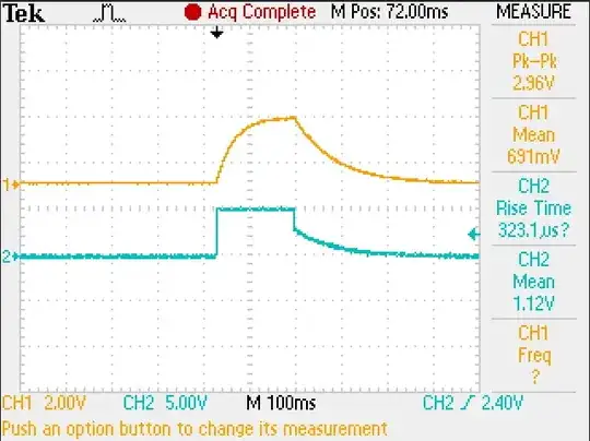
And obtained the following output:

Response

According to my professor, the charging and discharging of the capacitor has different time constants. Why is this the case?

Null
  • 7,448
  • 17
  • 36
  • 48
user3266738
  • 215
  • 5
  • 10
  • 1
    Why don't you ask him? – Leon Heller Nov 09 '14 at 14:50
  • 1
    When you discharge the capacitor its being discharged by the 470 ohm resistor. What impedance is used to charge it? You may want to look at [Thevenin](http://en.wikipedia.org/wiki/Th%C3%A9venin%27s_theorem) – Warren Hill Nov 09 '14 at 15:22
  • 1
    My suggestion would then be to change something. And see if you can understand that. More data! (change one of the resistor values.. see what happens. – George Herold Nov 09 '14 at 15:29

3 Answers3

1

For the closed switch (charging period) both resistors are active (in parallel). When the switch is open the 330k resistor is inactive (discharging period). Hence, the time constant for discharging is larger (470k*0.2µF).

The situation will be different when using a voltage step from 0 to 5V and back to zero (duration 0.5..1 sec, for example). In this case, both time constants will be identical.

LvW
  • 24,857
  • 2
  • 23
  • 52
1

Let's say \$R_1=330k\Omega\$ and \$R_2=470k\Omega\$

For charging, you can analyse the transfer function of the circuit with the switch closed.

\${V_{out}\over V_{in}}={{R_2\over sC}\over{R_2+{1\over sC}}}\cdot{1 \over {R_1+{{R_2\over sC}\over{R_2+{1\over sC}}}}}={R_2 \over R_1R_2sC+R_1+R_2}={{R_2\over{R_1+R_2}}\over1+sC{R_1R_2\over{R_1+R_2}}}={{R_2\over{R_1+R_2}}\over1+sC{(R_1||R_2)}}\$.

The charging time constant is therefore \$\tau_{charge}=C(R_1||R_2)=38.775 ms\$.

When discharging, however, current can only flow through \$R_2\$, as the source and \$R_1\$ are disconnected from the circuit. Therefore, the time constant is \$\tau_{discharge}=R_2C=94 ms\$.
hryghr
  • 1,179
  • 1
  • 8
  • 18
0

Well look at the circuit and try to understand what is going on.

When the switch is closed you will be charging the capacitor (along with letting current flow through the parallel resistor) through the small series resistor. The small resistor will result in a small RC time constant.

When the switch is open and the capacitor is already charged then you will be discharging the capacitor through the larger parallel resistor resulting in a high RC time constant.

This explains the behavior you are seeing.

secretformula
  • 288
  • 2
  • 21