5

I have looked through all the other 'what is this component' questions and have not found my component. I am looking for the component in the red box. It is from a rectifier circuit off a 1973 9.8 hp Mercury 110 Outboard. I ripped the silicon off the red plastic housing and this is what is underneath! I'm sure there is more than one person out there looking to source these parts.

Also I built the circuit in CircuitLab to see what it's like. The component in question is (F1).. you can see from the schematic it's a Bridge diode circuit. Right now the best guess on F1 is a fuse (I used to think it was a high wattage resistor - to drain transient current) If it's a Fuse, how is it being used successfully in this circuit? It doesn't seem to prevent any current from going to the output when blown.

schematic

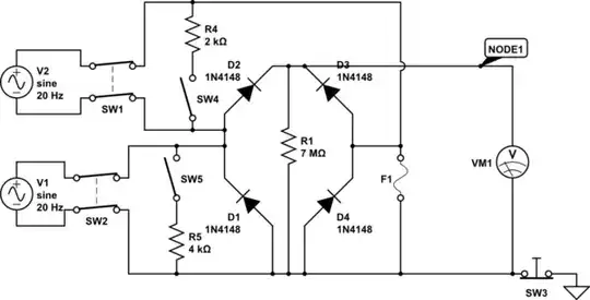
simulate this circuit – Schematic created using CircuitLab

The circuit has two oscillating inputs like I believe the ignitor coils see when the EMF is passing through them. The switch to short them is while the coil is just left there - acting as a resistor of sorts. It is a magnento type ignition system where both the magnets and ignitor coils are positioned 180 degrees from each other, so that both magnets pass over the coils at the same time, creating a voltage in each coil to power the spark.

SW1 - is the high speed coil (~2K ohms)
SW2 - is the low speed coil (~4K ohms)

Can anybody tell me what the component in the red box is? It looks like straight carbon - like from a brushed motor but have not had any luck finding it through google or online part warehouses (digikey, mouser, etc..).

* I now believe this to be a Ceramic Cartridge fuse but need verification before assuming that is correct.

Thanks in advance!

1973 Mercury 110 9.8 Rectifier

Treflip
  • 81
  • 6
  • 3
    So why would someone down vote this question? I need help that's why I came here.. Should I change something... I don't get it. Why would someone come to a site for questions and put the questions down instead of answering it or at least leave some feedback? – Treflip Nov 08 '14 at 23:23
  • 7
    That component in the box looks like a fuse to me, not a resistor. – RJR Nov 08 '14 at 23:38
  • Welcome, new user! I didn't downvote you, but I know the misterious user who did doesn't mean to be rude. It's that the first users of the site decided that questions about fixing electronic devices in which the poster didn't show good understanding of the design were off-topic here. So, your question does resemble a fix question, but can be also considered an "identify this component" (so you can fix the thing later). That's why the downvote I suppose. And [here's a list of what on- and off-topic here](http://electronics.stackexchange.com/help/on-topic) – Ricardo Nov 08 '14 at 23:41
  • So the first users of the site govern how the voting option is used? That's wierd. I believe I understand 80 percent of the circuit involved so I don't feel like I fall under the category of not showing good understanding. I can see the fixing the device part but didn't see anywhere in the faqs about not posting about electronics that need fixing... If there is unspoken rules and I break them then I don't feel bad or anything. Thanks for the welcoming! – Treflip Nov 08 '14 at 23:43
  • These first users and the SE folks defined what the scope of this site should be. That was back in 2009/2010 I suppose. Look at [Area 51](http://area51.stackexchange.com/) for more info on how stacks are created. – Ricardo Nov 08 '14 at 23:47
  • Well I looked through the first two links from your original post and my question had a schematic, was not open-ended, etc.. I believe it was a good fit for stackexchange! I don't see the need for the downvote. ***Not sure what the link to Area 51 was covering but thanks for links...maybe you can talk to the user that downvoted it and have them remove it since the question did not violate any terms here. Thanks! – Treflip Nov 08 '14 at 23:52
  • @RJR I looked up fuses and there is similarity with the ceramic cartridge fuse. I'm not quite sure how to verify if that is correct but am leaning heavily towards it. – Treflip Nov 09 '14 at 00:54
  • The link to Area 51 was to show you how new stacks and their scope are created. Votes are secret at SE, so there's no way to tell who the downvoter is. Don't worry much if you get one down vote here or there. Just pay attention if they start to build up. – Ricardo Nov 09 '14 at 02:08
  • @user3366449 FYI, within the microcosm of StackExchange there is a specialized stack [Mechanics.SE (motor vehicle maintenance and repair)](http://mechanics.stackexchange.com). When you find that you have posted a question to a wrong stack, you can make a flag to moderators and they will migrate it to a different stack (answers, comments, and all). I'm inclined to migrate this one to Mechanics.SE either right now, or to let it stew here on EE.SE for a day first. – Nick Alexeev Nov 09 '14 at 02:15
  • @NickAlexeev I can see where someone might think to post a question about a rectifier from an outboard 'motor' there but it does not fall under their list of cars, truck, and motorcycles, so it wouldn't be valid. It matches up with the frequently asked questions here (search ['what is this component'](http://electronics.stackexchange.com/search?q=what+is+this+component)) and I followed the rules when posting (as commented about earlier) so it's a relevant question to stackexchange.EE. Thanks for the link. I am excited to see a place where repair can be documented in an organized fashion! – Treflip Nov 09 '14 at 03:11
  • @Ricardo I believe this question falls under the scope of SE.EE. I am starting to question it though! Thanks for the heads up... I will consider it a small part of asking questions here and I guess gear myself up for it! I'm sure it be a benefit to myself and other readers in the end though. – Treflip Nov 09 '14 at 03:12
  • 2
    I believe that this question is relevant for this site. I don't see any reason why it should be migrated. Also along with the others I think that this is a fuse. – Adam Nov 09 '14 at 08:49
  • 1
    Looks more like a thermistor than a fuse, to me. Specifically, a "rod thermistor". (BTW there is no R2 on the schematic - did you re-label it F1?) A thermistor changes its resistance with temperature and may adjust the behaviour of this circuit with temperature (motor speed, power level). What would be the purpose of a fuse here? –  Nov 09 '14 at 11:39
  • If it's a thermistor ... How to confirm? can you get a measurement of resistance from one intact end to the fracture? If so, heat and see if resistance increases or decreases. That would give you a starting point for finding a replacement. –  Nov 09 '14 at 11:46
  • @BrianDrummond I believe if it was a rod thermistor there would be some resistance across it... or it should open/close when different temperatures are applied right? As of now there is no resistance and no short for that matter which makes it hard for me to be certain its a fuse... Also I did edit the post earlier and again to make it consistent. Sorry for the confusion! – Treflip Nov 09 '14 at 13:48
  • Just tried here on one that reads 470 ohms from one lead to the other. I can't get good contact on the body halfway down, but by pressing hard I can get unstable resistance readings from 10000 ohms upwards. (Too unstable to tell if it's NTC or PTC, but across the leads I can see it's NTC (reduces R as it warms up) –  Nov 09 '14 at 15:14
  • @BrianDrummond I couldn't tell what the fuse would be doing there seeing as the bottom diodes are grounded and potentially routing the positive spikes around it. I have a hunch it's for excess/ive current - the system generates up to 1000V (not sure the amperage though) and may need some protection from initial surging as well. – Treflip Nov 10 '14 at 03:23
  • Instead of all this fooling around, why not just go [here](http://www.crowleymarine.com/mercury-outboard/parts/458_30.cfm) or some place like it and find out for sure? – EM Fields Nov 15 '14 at 10:49
  • @EMFields This isn't fooling around. This is the way engineers figure out how to build things when they are too cheap to replace the whole component - See the actual item I am referring to [crowleymarine] (http://www.crowleymarine.com/parts/13331.cfm) from your link... to belabor the point as well, most manufacturers don't provide schematics for small parts like these because they can mark up by 4000% and get more money from you but I'd rather learn how the component works and save a lot of money - plus it keeps me out of trouble when I can't be out on the water fishing! ;) – Treflip Nov 15 '14 at 11:13
  • Be that as it may, it strikes me that you're not really trying to build/design anything, you're trying to find out what something **is** so that you can effect a repair on the cheap. Not that there's anything wrong with that, but it seems to me that you're trying to make a silk purse from a sow's ear. – EM Fields Nov 15 '14 at 11:42
  • @EMFields No not at all! This component isn't something I've seen before and needed help identifying it... as an added bonus- understanding the circuit and how it works is a plus... not just for me but for anyone interested in rectifiers circuits, ignition systems. Trust me once I figure out what the little guy is it will be quicker than two shakes of a lamb tail to get it together and working again! – Treflip Nov 15 '14 at 12:21
  • Oh come on people... So much talk of is this question relevant or not here is almost like politicians arguing and achieving nothing. My first guess when looking at it were either a fuse or a high powered resistor as well. Frankly, for my own future understanding I'd appreciate a clear answer for this question as well. Being able to identify ambiguous components in the wild is a good skill to have for any EE. – Jarrod Christman Nov 19 '14 at 12:17
  • @JarrodChristman Thanks for the vote of confidence. I'm glad to hear other people interested in finding out the component in question too! – Treflip Nov 20 '14 at 13:51

2 Answers2

1

The fuse F1 will protect V1 and V2 against SW1 and SW2 being closed simultaneously. Both switches closed together will cause a short circuit of the 2 voltage sources - depending on what these voltage sources are the current spike caused by a short circuit could be catastrophic.

gurn_bot
  • 11
  • 1
  • Thanks for the answer too! I added a little more detail on the magneto type ignition system to clarify. What you're saying is true, when both magnets pass over the ignitor coils (both switches are closed) at the same time current will flow through SW2 then SW1 (CW rotation) but this is the intended action to produce a spark later - the voltages add together. If the fuse was of great enough resistance then the current from SW1 would bypass going to ground and flow through Diode(D3) and out to Node1. Does this sound likely? – Treflip Nov 15 '14 at 12:36
0

It looks like a cheap, low resistance, high power, resistor (might be a thermistor). I recommend that you use a 5 ohm (or less), 10 watt, resistor as a replacement and measure the voltage drop across it and current to verify that 10 W is the appropriate power.

Guill
  • 2,430
  • 10
  • 6
  • Thanks for the answer! @BrianDrummond Thought this might be the case as well and I checked for resistance (see comments above) but can't get any recognizable measurement across it (including continuity - from one end to the broken end). Which makes it hard to see how it could be a fuse too. – Treflip Nov 15 '14 at 12:27