-1

I've tested controlling single 24VDC relay with Arduino by using external power source to power the relay. Now I've set up a board to control several of these relays, but noticed that the Arduino output does not trigger the relay it did before. I've looked but haven't found any threads about multiple relays and board configuration.

I noticed that when I removed all output pins from Arduino (only inputs from buttons connected), the Arduino worked flawlessly (led indication). Something seems to be affecting Arduino or the output pin section of the board or causing the relay not to function properly.

The problem is that Arduino does not seem to register the signal from the input when output pins are connected. Only after several pushes or long delay, the relay is triggered again.

Is there something that I could fix or add to the board to make it more reliable?

Could common 24 VDC rail be causing problems when there are several relays on the same board (is the position of the diode right when there are multiple relays)?

Arduino controlling multiple relays

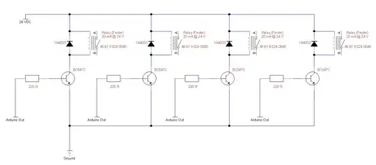
Relay specs: FINDER - 46 Series; Coil voltage and current: 24 VDC and 20 mA; Coil resistance: 1.2kohm. More details of the relay can be found from here: http://uk.farnell.com/finder/46-61-9-024-0074/relay-spco-16a-24vdc/dp/1329676

Jari
  • 1
  • 3
  • In the schematic, the ground is at the very top, and the positive supply rail is at the very bottom. Oh well, I'll simply turn the laptop upside-down. But seriously, please read these [rules and guidelines for drawing good schematics](http://electronics.stackexchange.com/q/28251/7036). They are useful. – Nick Alexeev Nov 07 '14 at 22:19

1 Answers1

1

\${{5\text V−0.7\text V}\over220\Omega} \approx 19.5\text{mA}\$

You cannot source that much sustained current from many outputs without damaging the device. Either increase the value of the 220\$\Omega\$ resistors or switch to something like a ULN2803A instead. As a bonus, the ULN' includes the clamp diodes.

Ignacio Vazquez-Abrams
  • 48,282
  • 4
  • 73
  • 102
  • Thanks. What size resistor would you recommend? – Jari Nov 07 '14 at 22:37
  • Take the lowest hfe for the transistor, divide the Ic by that, plug the result back into the equation above, and go 20% smaller. That should give you plenty of margin. – Ignacio Vazquez-Abrams Nov 07 '14 at 22:42
  • So are you saying I should use the lowest possible current that still activates the transistor? – Jari Nov 08 '14 at 13:12
  • Assuming the worst conditions for the transistor, yes. That way there will be plenty of current to go around. – Ignacio Vazquez-Abrams Nov 08 '14 at 13:20
  • Seems to be working with 6.8 K Ohm resistor. However, the first problem with Arduino not reacting correctly to button still has not vanished. I also noticed that sometimes (every tenth time or so) second button activates the same relay as the 1st button. Both buttons are marked as pullup and there is no voltage in buttons. Is there a way that the signal is somehow induced between buttons? – Jari Nov 10 '14 at 19:49
  • With 6.8 k Ohm resistor the voltage from Arduino to transistor base is 4.91VDC and current 0.55mA. Seems to work better now (no slowness). – Jari Nov 16 '14 at 10:56