0

I'm working on an experiment where I'd like to shift a 24V on/off signal down to 3.5V or 5V (i.e. suitable to use with an Arduino or Raspberry Pi).

For simplicity and safety - I really don't want to fry the equipment I'm working with - I decided to use an comparator rather than some sort of voltage divider. The ship I bought was a TI LM339N (datasheet here: http://www.datasheets360.com/pdf/4687091707087477802), as I have to eventually sense multiple signals.

As an experiment, I'm testing this with a 9V signal downshifting to 3V connected to an LED.

The wiring looks like this:

Wiring Diagram

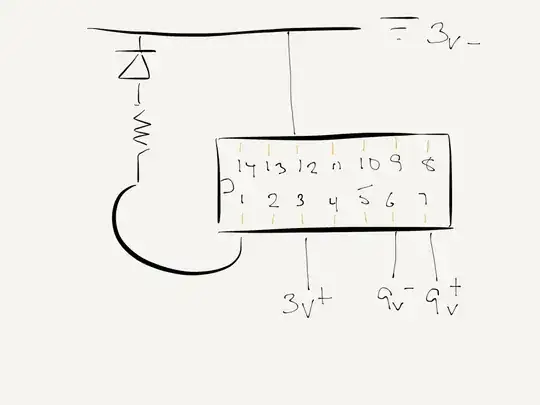
  • Pin 1: 1OUT: connected to Resister & LED. Tested separately to make sure it works
  • Pin 3: Vcc: 3V+
  • Pin 12: GND: 3V-
  • Pin 6: 1IN-: 9V-
  • Pin 7: 1IN+: 9V+

So I'm pretty sure I'm on the right track here. But I'm expecting the LED to be lit up, the logic (in my mind) being that there's a 9V difference between pins 6 & 7, so pin 1 should be and be showing 3V.

David Janes
  • 153
  • 4
  • 2
    Why did you decide to do it this way instead of using a NPN BJT? – Ignacio Vazquez-Abrams Nov 07 '14 at 21:03
  • Mainly based on what I have in cabinets here - I'm really new to hardware, which is probably why I'm making a lot of bad choices. Do you have a pointer to a sample circuit for this? – David Janes Nov 07 '14 at 21:34
  • http://electronics.stackexchange.com/questions/82104/single-transistor-level-up-shifter will work for downshifting if the pullup is removed. The high input goes to the emitter. – Ignacio Vazquez-Abrams Nov 07 '14 at 21:52

1 Answers1

3

The comparator is "open collector" meaning it cannot source current, it can only sink current.

If you flip the LED and connect it (with the series resistor) between the output and +3V you should see it work (assuming it's a red LED) if the inputs are biased correctly (and they are not).

Your test is not respecting the common mode range of the inputs- you should ground pin 6 as well as apply the (isolated) test voltage between pins 6 and 7. You cannot apply a negative voltage (don't flip the input polarity or you'll kill the chip) wrt ground (-300mV is absolute maximum wrt ground).

You cannot expect it to function properly with input voltages exceeding the supply voltage minus 2V or more, so with a 3V supply you should not apply less than -300mV or more than 1V to any input for proper operation.

If you want to compare a 24V signal you could use a supply voltage of 5V (the minimum recommended), generate a (say) 1V reference with a divider and divide the input signal down to (say) 0V/2V for on/off. Pull the output up to 3V and you'll get a 3V compatible output.

Or just use a transistor/diode and a few resistors as Ignacio suggests! Or use an optocoupler with a couple resistors to be very safe.

Spehro Pefhany
  • 376,485
  • 21
  • 320
  • 842