0

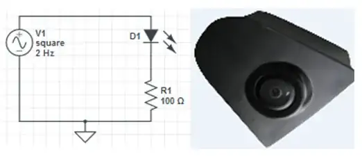
LED flashing light captured by camera

Displayed image detected by photodiode
Displayed image detected by Photodiode

I have a 2V p-p square wave signal of 500µs. This signal drives a LED and when I measure the waveform across the resistor connected in series with the LED I get a square waveform. I have a camera which is takes this flashing light as an input and this camera signal I am displaying on the display. I have designed a Photodiode circuit ( photodiode and 100K resistor in series ) having a supply of 5V and placed this circuit next to display in dark room. When the flashing light of LED taken by camera is displayed the Photodiode is activated. But the problem is I am not able to see the variation in waveform as when it is activating, output is directly 5V DC. I need to see the variation in square waveform. I Want to calculate delay between camera input and output at Display. Please help me out for getting square wave across photodiode so that I can see the difference in waveform from LED and Photodiode. Let me know where I am going wrong and what are the steps I should follow.

Photodiode info:

http://www.produktinfo.conrad.com/datenblaetter/150000-174999/153005-da-01-ml-PIN_PHOTODIODE_BPW34_OSR_de_en.pdf

chetan
  • 3
  • 4
  • show us a schematic diagram of the photodiode circuit. 100K Ohms in series sounds quite a lot! Also if you have a datasheet or part number at least for the major component/s you are using, might help us help you. – KyranF Nov 07 '14 at 08:58
  • Also, see if the answer to this question about photodiodes solves your problem: [How do I connect a photodiode?](http://electronics.stackexchange.com/a/33660/38969) – KyranF Nov 07 '14 at 09:02
  • Thanks KyranF for your suggestion. I have added the circuit which currently I am using. I am taking the output at both the resistors. input voltage - 2V P-P. – chetan Nov 07 '14 at 09:39
  • so the LED D1 turns on, visibly, yes? What is the LED's forward voltage? And you view the node between R2 and D2 with an oscilloscope, and you see no change in voltage? – KyranF Nov 07 '14 at 09:50
  • LED forward voltage is 1.8V. I can also see a square wave on oscilloscope across the R1. So my requirement is to see the square wave at R2. Purpose is to see how much delay is there in between these two waveforms. But I am confuse about how to manage a circuit using Photodiode to get a square waveform. Currently with 5V DC supply I am getting 100mV DC output at R2. The light is fluctuating so as per my understanding when there is light on and off, Phodtodiode should also behave the same way like voltage high and low ( square wave). But its not the same as i understood. Please correct me. – chetan Nov 07 '14 at 10:00
  • at 1000 Lux it's meant to put through about 80 microamps, or at least 50microamps anyway. What is your LED colour/wavelength? You say that you see 100mV on R2, does this EVER change? – KyranF Nov 07 '14 at 10:05
  • there is small correction. Forward voltage of LED is 2.2V. No, the voltage at R2 doesnt change even I tried puting diode in total black area and ony LED light on it and then I also tried it with actual light without any black area. But there is no changes in voltage level. It seems like you are giving a supply and its working like normal diode. till now I have not seen actual operation of Photodiode in here. – chetan Nov 07 '14 at 10:19
  • To clarify. You are driving a square wave and generating light in a LED. This light is received by a camera and then displayed on a monitor or computer display. You are then measuring when the light appears on the display with your Photodiode. Is this correct? IF so what are you trying to measure? The time delay through the camera and into the display? The time delay of the camera by itself? – placeholder Nov 07 '14 at 13:55
  • its not a monitor display. Its small display like display we use in cars. I just made an arrangement of this camera in one box with LED and resistor circuit, and the display with photodiode and resistor in other box so when LED flash a light this frame captured by camera and then this frame is getting diplayed on small display. here I have put the photodiode along with resistor in front of the display and this set up is totally in dark box so that only display light that to only LED's flash light will be detected by photodiode. – chetan Nov 07 '14 at 14:06
  • You diagram is misleading, you are missing the camera and display. You should draw that in otherwise people will solve the simpler problem of a LED driving a detector. – placeholder Nov 07 '14 at 14:09

2 Answers2

0

There are several areas in which this can be complicated:

First of all the camera with have an integrating period, this will tend to blur out your wave form edges so your the precise timing won't be easily determined. i.e. your edges will be blurred. This is a consideration for when you get the circuit going.

You don't say what your display is, but it is entirely possible that your display is generating too much light in it's "off" state. Most LCDs have a finite contrast ratio and leak light in the off state. You can see this is a darkened room easily. So if it always on then your photodiode is too sensitive or there is stray light interfering with the PD.

Maybe shroud the detector so room light cannot get in.

If you are getting only small amount of signal at your PD then it's possible that the display does not generate light for the photodiode. You can solve that with additional circuitry (a gain stage) or with a phototransistor.

placeholder
  • 29,982
  • 10
  • 63
  • 110
  • Yes you are right. Display is generating some light even LED is in its OFF state. And may be this is affecting on Photodiode. I tried shrouding the detector but as LCD light is there so its giving the same output on Oscilloscope. – chetan Nov 07 '14 at 15:12
  • @chetan then what you can do is build a detector circuit that has a) gain and b) an adjustable offset so you can subtract off the "background" light of the LCD dark state. It's just a few more components. – placeholder Nov 07 '14 at 15:46
  • Thank you very much for the suggestion. I will do the same. – chetan Nov 07 '14 at 16:00
  • @chetan, it looks like your photodiode is operating in reverse bias mode, correct? Are you sure your diode doesn't have a higher reverse bias voltage than 5V? I have a few that are as high as 30VDC. A higher reverse voltage allows more current to flow, and thus a higher voltage potential across your sensing resistor. Just beware that this also increases your dark current output as well. Ideally, you'd want to make a bandpass filter for the band you're operating within, then have a gain stage of some sort. – Jarrod Christman Nov 07 '14 at 20:13
  • Phototransistors are another route, except for their response tends to be a lot slower... but considering you show a 2 hz waveform, you should be fine there. Can you not operate at a higher frequency? Would make filtering a lot easier. – Jarrod Christman Nov 07 '14 at 20:15
  • Thank you Jarrod for your comments. First of all, my requirment is to check the difference between input waveform and output waveform. I have chosen 2Hz signal so that I can blink LED in slow manner to see the variations at the photdetector side. but unfortunately I am unable to see these variations. regarding reverse voltage, yes it has 32V max reverse voltage. Could you please tell me what will be the role of bandpass filter. thanks in advance – chetan Nov 10 '14 at 08:05
  • @JarrodChristman, Just a small correction. A larger reverse bias across the PD will not give you any bigger signal. (V = I(PD) * Rsense) (unless the light level is such that almost all the the bias falls across the sense resistor... until the light forward biases the PD.) What the reverse bias does do is reduce the capacitance of the PD and this will make the circuit faster. – George Herold Nov 10 '14 at 13:38
  • @GeorgeHerold, thank you for the correction, will make a mental note of that. Chetan, it is not a requirement to use a bandpass filter, but when you amplify the signal you also amplify the noise, thus it is good to apply a filter to remove as much of the noise elements as possible. I'd suggest trying a higher frequency and see if you get better results, 2 hz is so close to DC you may have a hard time seeing it when you take parasitic capacitance and inductance into account. – Jarrod Christman Nov 10 '14 at 14:16
  • Thanks Jarrod for your suggestion. Can you tell me how much frequency I should try in this case. – chetan Nov 11 '14 at 09:33
0

This is a confusing question. But just a few observations/ questions.
I assume you can see that the LED is on. (It's not an IR LED, and there is enough drive to turn the LED on.)
If that's the case then your photodiode detector looks fine. Monitor the voltage across the 100k ohm resistor with your 'scope probe.

George Herold
  • 4,754
  • 1
  • 18
  • 25
  • Thank you for your comment. Yes I am monitoring the waveform across 100k resistor. I am expecting a square wave but its showing 100mV constant waveform, not even a fluctuation in it. – chetan Nov 10 '14 at 08:01
  • @chetan, I'm still confused. Are you putting the PD in front of the LED or in front of your display? (The later would most likely give a constant output.) – George Herold Nov 10 '14 at 13:39
  • PD infront of Display. There are two seperate set ups. 1- Camera infront of LED, 2- PD infront of Display. And I made this setups in two different boxes. – chetan Nov 10 '14 at 15:23
  • @chetan, OK So what the "bleep" are your trying to do? Would this work? Get two leds and run them in series so they both turn on at the same time. Send one into your photodiode and the other into your Camera. – George Herold Nov 10 '14 at 15:45
  • I am gettting the proper LED spot as well as blinking on my LCD display. So when LED is in OFF state, there is no blinking on the display but at this time there is a light of LCD itself which stops photdiode by going in OFF state. SO for whole time photodiode is in ON state only and because of this I cannot see the variations in the output. – chetan Nov 11 '14 at 09:22